Nissan Cube. Manual - part 944


  Index      Nissan     Nissan Cube (2014 year) - Service and Repair Manual


Search            


Content   ..  942  943  944  945   ..


Nissan Cube. Manual - part 944


TM-32

< UNIT DISASSEMBLY AND ASSEMBLY >

[6MT: RS6F94R]

TRANSAXLE ASSEMBLY

Disassembly

INFOID:0000000009948882

1.

Remove drain plug and gasket from clutch housing, using a socket [Commercial service tool] and then
drain gear oil.

2.

Remove filler plug and gasket from transaxle case.

3.

Remove selector lever (1) retaining pin with a pin punch to
remove selector lever.

4.

Remove bracket (2) and position switch (3) from transaxle case.
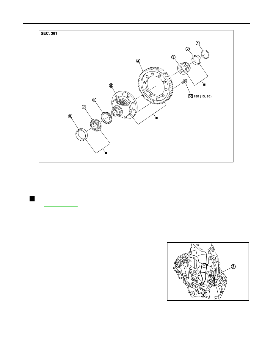
1.

Shim

2.

Differential side bearing outer race 
(transaxle case side)

3.

Differential side bearing inner race 
(transaxle case side)

4.

Final gear

5.

Differential case

6.

Speedometer drive gear

7.

Differential side bearing inner race 
(clutch housing side)

8.

Differential side bearing outer race 
(clutch housing side)

: Replace the parts as a set.

Refer to 

GI-4, "Components"

 for symbols not described on the above.

JPDIC0604GB

PCIB1693E

TRANSAXLE ASSEMBLY

TM-33

< UNIT DISASSEMBLY AND ASSEMBLY >

[6MT: RS6F94R]

C

E

F

G

H

I

J

K

L

M

A

B

TM

N

O

P

5.

Remove transaxle case mounting bolts (

).

6.

Remove reverse idler shaft mounting bolt (

) and seal washer.

7.

Remove transaxle case (2) while rotating shifter lever A (1) in
the direction as shown in the figure.

8.

Remove selector spring (1) from return bushing (A).

9.

Shift 1st-2nd fork rod (1), fork rod (2), and reverse fork rod (3) to
the neutral position.

10. Remove selector (4) from clutch housing.

PCIB1694E

PCIB1695E

JPDIC0444ZZ

JPDIC0445ZZ

PCIB1698E

TM-34

< UNIT DISASSEMBLY AND ASSEMBLY >

[6MT: RS6F94R]

TRANSAXLE ASSEMBLY

11. Remove reverse idler shaft assembly (1) according to the follow-

ing procedures.

a.

Pull up input shaft assembly (2), mainshaft assembly (3), fork
rod (4), and 1st-2nd fork rod (5).
NOTE:
It is easier to pull up when shifting each fork rod to each shaft
side.

b.

Remove reverse idler shaft assembly and reverse fork rod (6)
from clutch housing.

12. Remove spring washer from clutch housing.

13. Pull up and remove input shaft assembly (1), mainshaft assem-

bly (2), fork rod (3), and 1st-2nd fork rod (4) from clutch housing.
NOTE:
It is easier to pull up when shifting each fork rod to each shaft
side.

14. Remove final drive assembly (1) from clutch housing.

15. Remove magnet from clutch housing.

16. Remove differential side oil seals (1) from clutch housing and

transaxle case.

CAUTION:

Never damage clutch housing and transaxle case.

17. Remove differential side bearing outer race (1) from clutch hous-

ing, using a brass rod.

CAUTION:

Never damage clutch housing.

JPDIC0606ZZ

JPDIC0607ZZ

PCIB1703E

PCIB1704E

PCIB1716E

TRANSAXLE ASSEMBLY

TM-35

< UNIT DISASSEMBLY AND ASSEMBLY >

[6MT: RS6F94R]

C

E

F

G

H

I

J

K

L

M

A

B

TM

N

O

P

18. Remove differential side bearing outer race (1) from transaxle

case, using a brass rod.

CAUTION:

Never damage transaxle case.

19. Remove shim (2) from transaxle case.

20. Remove shifter lever A (1) retaining pin, using a pin punch.
21. Remove shifter lever A from transaxle case.

22. Remove shifter lever B (1) from transaxle case.

23. Remove oil gutter (1) from transaxle case.

24. Remove bushings (1) from transaxle case, using a remover

[Commercial service tool].

CAUTION:

Never damage transaxle case.

PCIB1705E

JPDIC0106ZZ

PCIB1712E

PCIB1707E

PCIB1710E


Content   ..  942  943  944  945   ..