Nissan Cube. Manual - part 941


  Index      Nissan     Nissan Cube (2014 year) - Service and Repair Manual


Search            


Content   ..  939  940  941  942   ..


Nissan Cube. Manual - part 941


TM-20

< REMOVAL AND INSTALLATION >

[6MT: RS6F94R]

CONTROL LINKAGE

8.

Remove clips from the air duct and air cleaner case. 

TM-22, "Removal and Installation"

.

9.

Remove air cleaner case and air ducts. Refer to 

EM-24, "Removal and Installation"

.

10. Pull out and disconnect the each cable from the shifter lever A and the selector lever, using a suitable

remover.

11. Remove each lock plate upward to disconnect the each cable from the cable mounting bracket.
12. Remove cable mounting bracket from the transaxle case.

13. Remove center muffler, exhaust front tube, and heat plate. Refer to 

EX-5, "Removal and Installation"

.

14. Remove bracket from the vehicle.

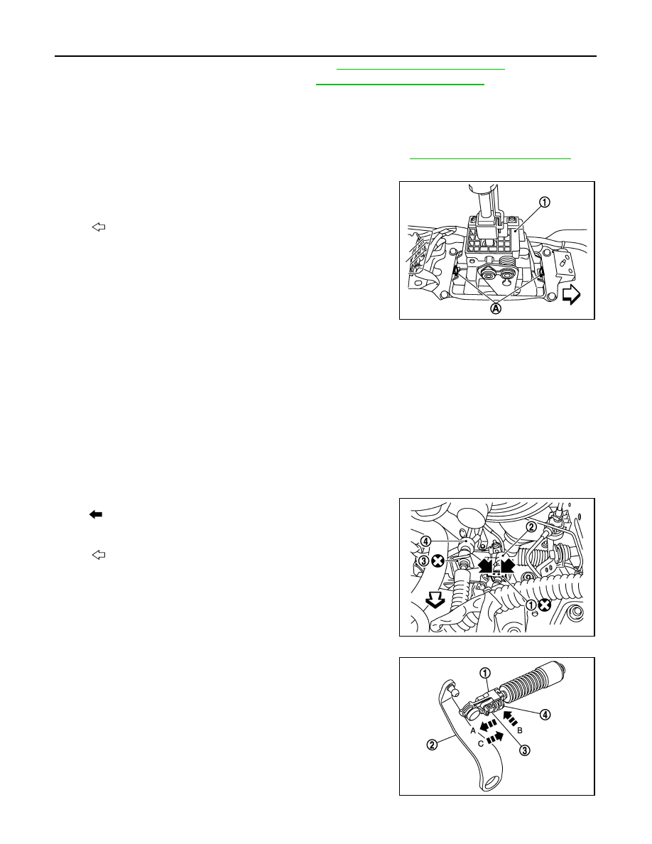
15. Release the tabs (A) on the front and back of the M/T shift selec-

tor (1) to remove the M/T shift selector from under the vehicle.

INSTALLATION

Note the following, and install in the reverse order of removal.

• To install the shifter lever knob, press it into the shifter lever.

CAUTION:

• Never reuse shifter lever knob.
• Be careful with orientation of shifter lever knob.

• Shift the shifter lever in the neutral position.
• Tapping work for tapping bolts is not applied to new transaxle case. Do not perform tapping by other than

screwing tapping bolts because tapping is formed by screwing tapping bolts into transaxle case.

CAUTION:

Never reuse tapping bolt.

• Shift the shifter lever A in the neutral position.
• Insert the each cable until it reaches the shifter lever A and the selector lever.
• The lock plate (1) which fixes the selector cable (2) has an indenta-

tion (

). Never confuse the lock plate with the lock plate (3) which

fixes the shifter cable (4).

• Insert the each lock plate until it reaches the cable mounting

bracket.

Install the selector cable according to the following instructions.

1.

Install the selector cable (1) on the cable mounting bracket to
install the lock plate.

2.

Install the selector cable on the selector lever (2).

3.

Slide the stopper (3) in the direction of the arrow (A) shown in
the figure.

4.

Press the lock (4) in the direction of the arrow (B) shown in the
figure.

CAUTION:

Never move the selector lever.

5.

Side the stopper in the direction of the arrow (C) shown in the
figure.

CAUTION:

Never move the selector lever.

: Vehicle front

JPDIC0658ZZ

: Vehicle front

JPDIC0659ZZ

JPDIC0709ZZ

CONTROL LINKAGE

TM-21

< REMOVAL AND INSTALLATION >

[6MT: RS6F94R]

C

E

F

G

H

I

J

K

L

M

A

B

TM

N

O

P

Inspection

INFOID:0000000009948873

INSPECTION AFTER INSTALLATION

• Check that the shifter lever knob maintains its position.
• Operate the shifter lever in each position to check that the shifter lever smoothly operates without any com-

plication, snag, noise, backlash, or interference. If any malfunction is fund, repair malfunctioning parts or
replace the M/T shift selector.

• Check that the shifter lever automatically and smoothly returns to the neutral position when selecting the 1st-

2nd side and the 5th-6th side. If any malfunction is fund, repair malfunctioning parts or replace the M/T shift
selector.

TM-22

< REMOVAL AND INSTALLATION >

[6MT: RS6F94R]

AIR BREATHER HOSE

AIR BREATHER HOSE

Exploded View

INFOID:0000000009948874

Removal and Installation

INFOID:0000000009948875

REMOVAL

1.

Remove air duct (inlet). Refer to 

EM-24, "Removal and Installation"

.

2.

Remove clip from the air duct.

3.

Remove air duct. Refer to 

EM-24, "Removal and Installation"

.

4.

Remove clip from the air cleaner case.

5.

Remove air breather hose from the 2 way connector.

CAUTION:

When removing air breather hose, be sure to hold 2 way connector securely.

INSTALLATION

Note the following, and install in the reverse order of removal.
• When installing air breather hose on 2 way connector, aim paint mark face toward the vehicle front.
• When installing air breather hose on 2 way connector, push it until it hits transaxle case.
• When installing air breather hose to air cleaner case, make sure that clip are fully inserted.

CAUTION:

Make sure that air breather hose is not collapsed or blocked due to folding or bending when
installed.

1.

Air cleaner case

2.

Air breather hose

3.

Air duct

4.

Clip

5.

Transaxle assembly

6.

2 way connector

SCIA7629E

POSITION SWITCH

TM-23

< REMOVAL AND INSTALLATION >

[6MT: RS6F94R]

C

E

F

G

H

I

J

K

L

M

A

B

TM

N

O

P

POSITION SWITCH

Exploded View

INFOID:0000000009948876

Removal and Installation

INFOID:0000000009948877

REMOVAL

1.

Filler plug

2.

Gasket

3.

Transaxle case

4.

Bushing

5.

Snap ring

6.

Oil channel

7.

Oil gutter

8.

Position switch

9.

Bracket

10. Differential side oil seal

11. Magnet

12. Drain plug

13. Input shaft oil seal

14. Clutch housing

15. 2 way connector

16. Plug

17. Pinion shaft

18. Pinion gear

: Apply Genuine Silicone RTV or an equivalent. Refer to 

GI-22, "Recommended Chemical Products and Sealants"

.

Refer to 

GI-4, "Components"

 for symbols not described on the above.

JPDIC0437GB


Content   ..  939  940  941  942   ..