Nissan Cube. Manual - part 805


  Index      Nissan     Nissan Cube (2014 year) - Service and Repair Manual


Search            


Content   ..  803  804  805  806   ..


Nissan Cube. Manual - part 805


DIAGNOSIS SYSTEM (BCM)

SEC-31

< SYSTEM DESCRIPTION >

[WITH INTELLIGENT KEY SYSTEM]

C

D

E

F

G

H

I

J

L

M

A

B

SEC

N

O

P

IMMU : CONSULT Function (BCM - IMMU)

INFOID:0000000009950100
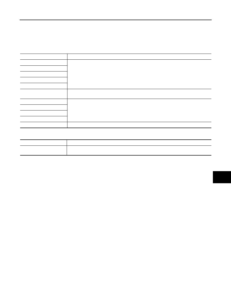
DATA MONITOR

NOTE:
The following table includes information (items) inapplicable to this vehicle. For information (items) applicable
to this vehicle, refer to CONSULT display items.

ACTIVE TEST

Monitor item 

Content

CONFRM ID ALL

Indicates [YET] at all time.
Switches to [DONE] when a registered Intelligent Key backside is contacted to push-button ignition 
switch.

CONFIRM ID4

CONFIRM ID3

CONFIRM ID2

CONFIRM ID1

NOT REGISTERED

Indicates [ID OK] when key ID that is registered is received or is not yet received. Indicates [ID NG] 
when key ID that is not registered is received.

TP 4

Indicates the number of IDs that are registered.

TP 3

TP 2

TP 1

PUSH SW

Indicates [ON/OFF] condition of push-button ignition switch.

Test item

Description

THEFT IND

This test is able to check security indicator lamp operation.
Security indicator lamp is turned on when “ON” on CONSULT screen touched.

SEC-32

< SYSTEM DESCRIPTION >

[WITH INTELLIGENT KEY SYSTEM]

DIAGNOSIS SYSTEM (IPDM E/R)

DIAGNOSIS SYSTEM (IPDM E/R)

CONSULT Function (IPDM E/R)

INFOID:0000000010251891

APPLICATION ITEM

CONSULT performs the following functions via CAN communication with IPDM E/R.

SELF DIAGNOSTIC RESULT

Refer to 

PCS-32, "DTC Index"

.

DATA MONITOR

NOTE:
The following table includes information (items) inapplicable to this vehicle. For information (items) applicable
to this vehicle, refer to CONSULT display items.

Diagnosis mode

Description

Ecu Identification

Allows confirmation of IPDM E/R part number.

Self Diagnostic Result

Displays the diagnosis results judged by IPDM E/R.

Data Monitor

Displays the real-time input/output data from IPDM E/R input/output data.

Active Test

IPDM E/R can provide a drive signal to electronic components to check their operations.

CAN Diag Support Monitor

The results of transmit/receive diagnosis of CAN communication can be read.

Monitor Item

[Unit]

MAIN SIG-

NALS

Description

MOTOR FAN REQ
[1/2/3/4]

×

Displays the value of the cooling fan speed request signal received from ECM via 
CAN communication.

AC COMP REQ
[Off/On]

×

Displays the status of the A/C compressor request signal received from ECM via 
CAN communication.

TAIL&CLR REQ
[Off/On]

×

Displays the status of the position light request signal received from BCM via CAN 
communication.

HL LO REQ
[Off/On]

×

Displays the status of the low beam request signal received from BCM via CAN 
communication.

HL HI REQ
[Off/On]

×

Displays the status of the high beam request signal received from BCM via CAN 
communication.

FR FOG REQ
[Off/On]

×

Displays the status of the front fog light request signal received from BCM via 
CAN communication.

FR WIP REQ
[Stop/1LOW/Low/Hi]

×

Displays the status of the front wiper request signal received from BCM via CAN 
communication.

WIP AUTO STOP
[STOP P/ACT P]

×

Displays the status of the front wiper auto stop signal judged by IPDM E/R.

WIP PROT
[Off/BLOCK]

×

Displays the status of the front wiper fail-safe operation judged by IPDM E/R.

IGN RLY1 -REQ
[Off/On]

Displays the status of the ignition switch ON signal received from BCM via CAN 
communication.

IGN RLY
[Off/On]

×

Displays the status of the ignition relay judged by IPDM E/R.

PUSH SW
[Off/On]

Displays the status of the push-button ignition switch judged by IPDM E/R.

INTER/NP SW
[Off/On]

Displays the status of the clutch interlock switch (M/T models) or shift position 
(CVT models) judged by IPDM E/R.

ST RLY CONT
[Off/On]

Displays the status of the starter relay status signal received from BCM via CAN 
communication.

IHBT RLY -REQ
[Off/On]

Displays the status of the starter control relay signal received from BCM via CAN 
communication.

DIAGNOSIS SYSTEM (IPDM E/R)

SEC-33

< SYSTEM DESCRIPTION >

[WITH INTELLIGENT KEY SYSTEM]

C

D

E

F

G

H

I

J

L

M

A

B

SEC

N

O

P

ACTIVE TEST

ST/INHI RLY
[Off/ ST ON/INHI ON/UNKWN]

Displays the status of the starter relay and starter control relay judged by IPDM 
E/R.

DETENT SW
[Off/On]

Displays the status of the CVT shift selector (detention switch) judged by IPDM E/
R.

S/L RLY -REQ
[Off/On]

NOTE:
The item is indicated, but not monitored.

S/L STATE
[LOCK/UNLOCK/UNKWN]

NOTE:
The item is indicated, but not monitored.

DTRL REQ
[Off/On]

NOTE:
The item is indicated, but not monitored.

OIL P SW
[Open/Close]

Displays the status of the oil pressure switch judged by IPDM E/R.

HOOD SW
[Off/On]

NOTE:
The item is indicated, but not monitored.

THFT HRN REQ
[Off/On]

Displays the status of the theft warning horn request signal received from BCM 
via CAN communication.

HORN CHIRP
[Off/On]

Displays the status of the horn reminder signal received from BCM via CAN com-
munication.

Monitor Item

[Unit]

MAIN SIG-

NALS

Description

Test item

Operation

Description

HORN

On

Operates horn relay for 20 ms.

FRONT WIPER

Off

OFF

Lo

Operates the front wiper relay.

Hi

Operates the front wiper relay and front wiper high relay.

MOTOR FAN

1

OFF

2

Operates the cooling fan relay (LO operation).

3

Operates the cooling fan relay (HI operation).

4

EXTERNAL LAMPS

Off

OFF

TAIL

Operates the tail lamp relay.

Lo

Operates the headlamp low relay.

Hi

Operates the headlamp low relay and ON/OFF the headlamp high relay at 1 sec-
ond intervals.

Fog

Operates the front fog lamp relay.

SEC-34

< DTC/CIRCUIT DIAGNOSIS >

[WITH INTELLIGENT KEY SYSTEM]

P1610 LOCK MODE

DTC/CIRCUIT DIAGNOSIS

P1610 LOCK MODE

Description

INFOID:0000000009950102

ECM forcibly switches to the mode that inhibits engine start, when engine start operation is performed 5 times
or more while communication between ECM and BCM is not normal.

DTC Logic

INFOID:0000000009950103

DTC DETECTION LOGIC

DTC CONFIRMATION PROCEDURE

1.

PERFORM DTC CONFIRMATION PROCEDURE

1.

Turn ignition switch ON.

2.

Check “Self-diagnosis result” using CONSULT.

Is DTC detected?

YES

>> Go to 

SEC-34, "Diagnosis Procedure"

.

NO

>> INSPECTION END

Diagnosis Procedure

INFOID:0000000009950104

1.

CHECK ENGINE START FUNCTION

1.

Perform the check for DTC except DTC P1610.

2.

Use CONSULT to erase DTC after fixing.

3.

Turn ignition switch OFF.

4.

Turn ignition switch ON when registered Intelligent Key backside is contacted to push-button ignition
switch and wait for 5 seconds.

5.

Turn the ignition switch OFF and wait 5 seconds.

6.

Repeat steps 4 and 5 twice (a total of 3 times).

7.

Check that engine can start when registered Intelligent Key backside is contacted to push-button ignition
switch.

>> INSPECTION END

DTC No.

Trouble diagnosis name

DTC detecting condition

Possible cause

P1610

LOCK MODE

When ECM detects a communication malfunction between 
ECM and BCM 5 times or more


Content   ..  803  804  805  806   ..