Nissan Cube. Manual - part 797
SE-20
< REMOVAL AND INSTALLATION >
REAR SEAT
Install the hog rings of seatback trim in position, and then securely connect the trim or trim cord with
the seatback frame.
SEAT CUSHION
Disassembly
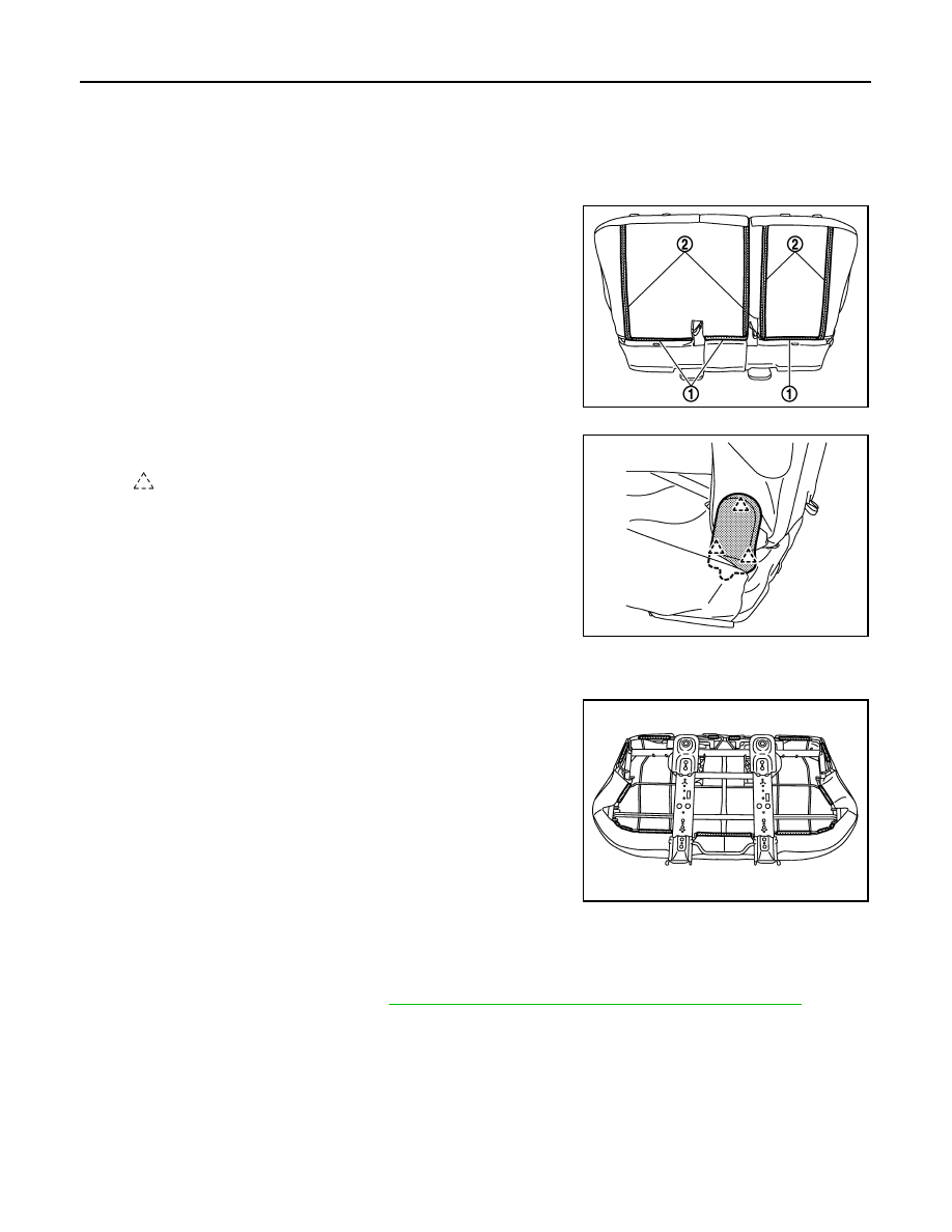
1.
Remove the seatback assembly.
• Remove the seatback retainers (1), and then open the fasten-
ers (2).
• Remove the pawls, and then remove outer hinge finisher.
• Remove the mounting bolts (inside, outside), and then remove seatback frame.
2.
Remove the seat cushion trim and seat cushion pad.
• Remove the seat cushion retainers from seat cushion back
side.
• Remove the seat cushion trim and seat cushion pad from seat cushion frame.
• Remove the hog rings to separate the seat cushion trim and seat cushion pad.
3.
Remove the seat cushion silencer.
4.
Remove the seat belt buckle. Refer to
SB-13, "SEAT BELT BUCKLE : Removal and Installation"
JMJIA2940ZZ
: Pawl
JMJIA2942ZZ
JMJIA2943ZZ