Nissan Cube. Manual - part 714
PCS
B2615 BLOWER RELAY CIRCUIT
PCS-81
< DTC/CIRCUIT DIAGNOSIS >
[POWER DISTRIBUTION SYSTEM]
C
D
E
F
G
H
I
J
K
L
B
A
O
P
N
4.
Check continuity between blower relay harness connector and ground.
Is the inspection result normal?
YES
>> GO TO 6.
NO
>> Repair or replace harness.
3.
CHECK BLOWER RELAY GROUND CIRCUIT
1.
Turn ignition switch OFF.
2.
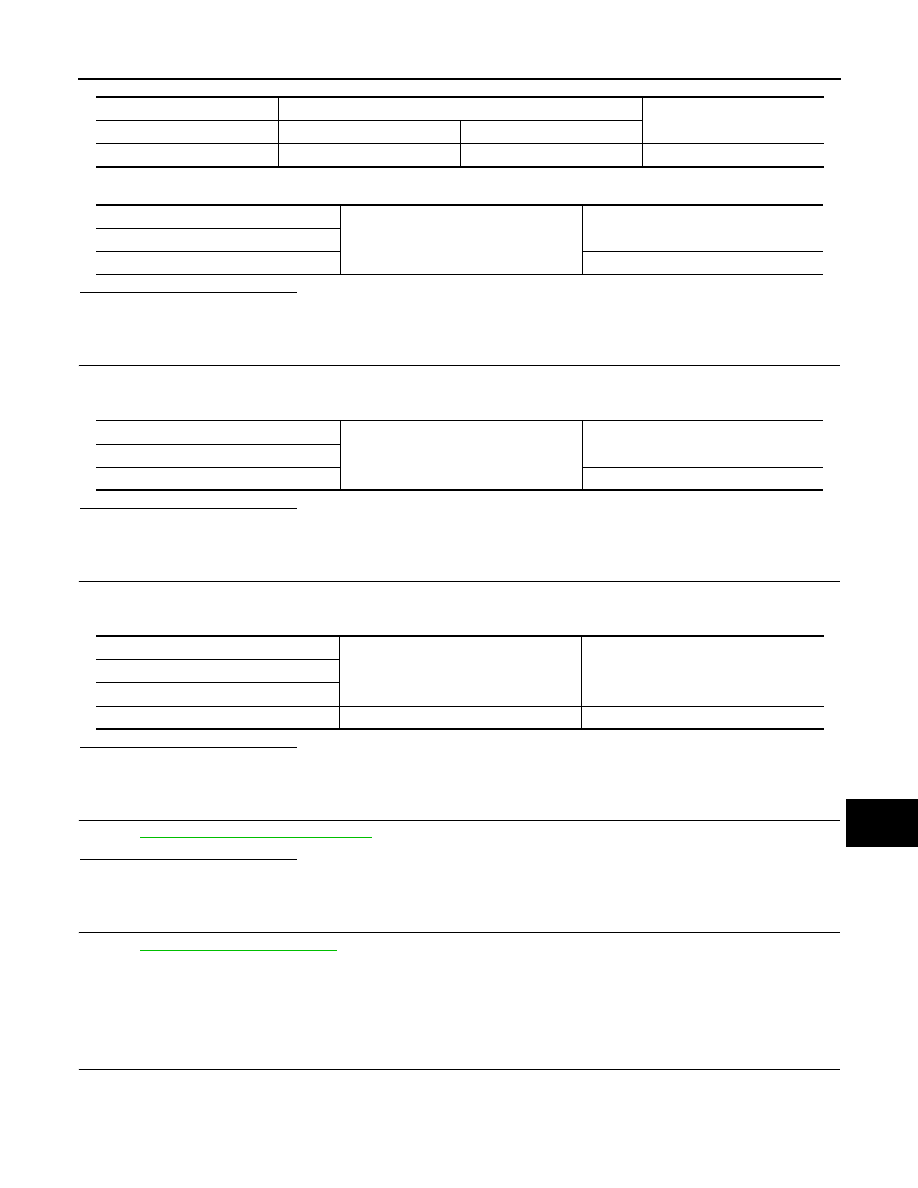
Check continuity between blower relay harness connector and ground.
Is the inspection result normal?
YES
>> GO TO 4.
NO
>> Repair blower relay ground circuit.
4.
CHECK BLOWER RELAY POWER SUPPLY CIRCUIT-2
1.
Turn ignition switch ON or ACC.
2.
Check voltage between blower relay harness connector and ground.
Is the inspection result normal?
YES
>> GO TO 5.
NO
>> Check continuity open or short between blower relay and battery.
5.
CHECK BLOWER RELAY
PCS-81, "Component Inspection"
.
Is the inspection result normal?
YES
>> GO TO 6.
NO
>> Replace blower relay.
6.
CHECK INTERMITTENT INCIDENT
GI-40, "Intermittent Incident"
.
>> INSPECTION END
Component Inspection
INFOID:0000000009945057
1.
CHECK BLOWER RELAY
1.
Turn ignition switch OFF.
2.
Remove blower relay.
Blower relay
BCM
Continuity
Terminal
Connector
Terminal
1
M71
106
Existed
Blower relay
Ground
Continuity
Terminal
1
Not existed
Blower relay
Ground
Continuity
Terminal
2
Existed
(+)
(–)
Voltage (V)
(Approx.)
Blower relay
Terminal
5
Ground
Battery voltage