Nissan Cube. Manual - part 715
PCS
B2616 IGNITION RELAY CIRCUIT
PCS-85
< DTC/CIRCUIT DIAGNOSIS >
[POWER DISTRIBUTION SYSTEM]
C
D
E
F
G
H
I
J
K
L
B
A
O
P
N
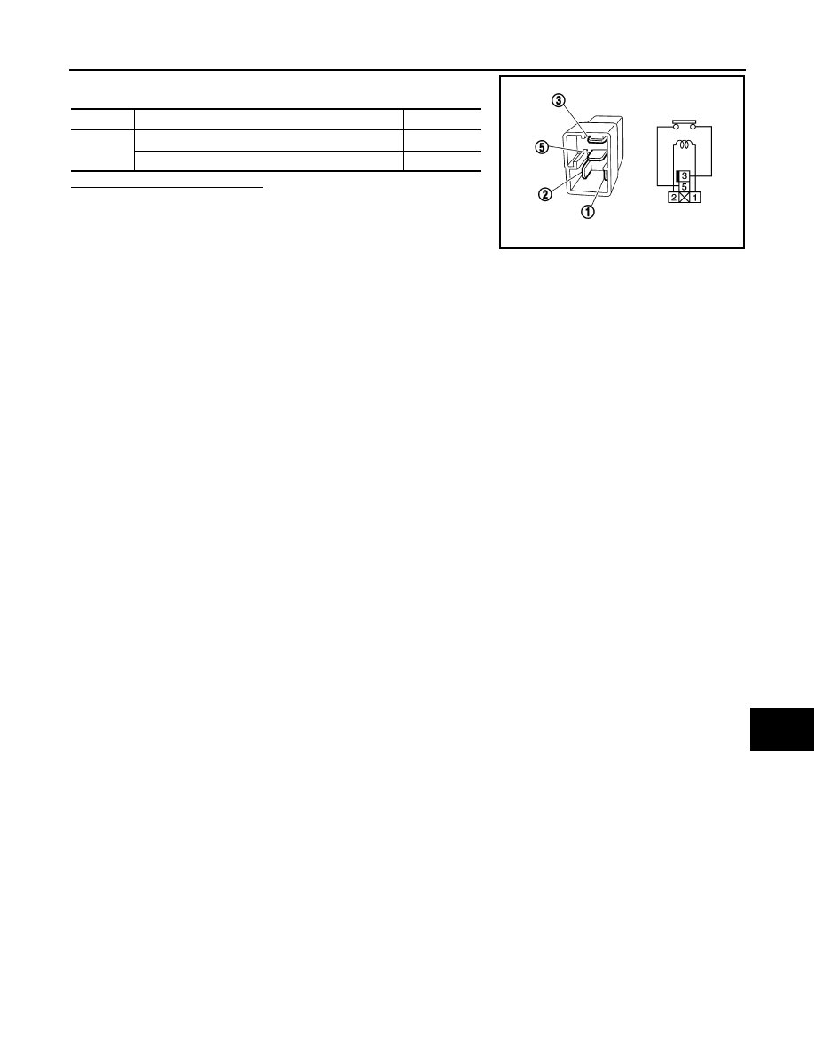
3.
Check the continuity between ignition relay terminals.
Is the inspection result normal?
YES
>> INSPECTION END
NO
>> Replace Ignition relay
Terminals
Condition
Continuity
3 and 5
12 V direct current supply between terminals 1 and 2
Existed
No current supply
Not existed
PBIB0098E