Nissan Cube. Manual - part 681


  Index      Nissan     Nissan Cube (2014 year) - Service and Repair Manual


Search            


Content   ..  679  680  681  682   ..


Nissan Cube. Manual - part 681


MWI-48

< ECU DIAGNOSIS INFORMATION >

COMBINATION METER

ECU DIAGNOSIS INFORMATION

COMBINATION METER

Reference Value

INFOID:0000000009945723

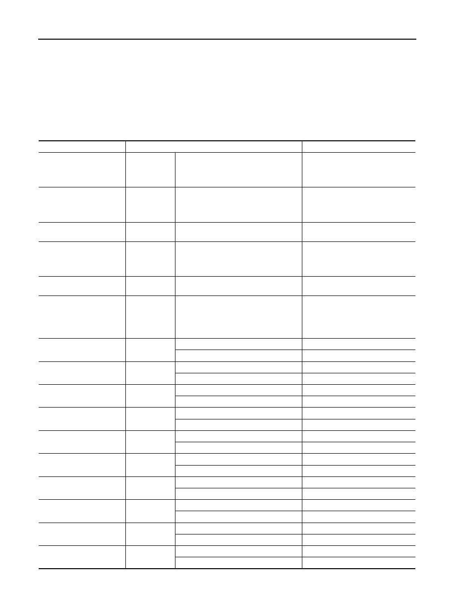
VALUES ON THE DIAGNOSIS TOOL

NOTE:
The following table includes information (items) inapplicable to this vehicle. For information (items) applicable
to this vehicle, refer to CONSULT display items.

Monitor Item

Condition

Value/Status

SPEED METER
[km/h]

Ignition switch 
ON

While driving

Equivalent to speedometer reading
NOTE:
655.35 is displayed when the malfunc-
tion signal is received

SPEED OUTPUT
[km/h]

Ignition switch 
ON

While driving

Equivalent to speedometer reading
NOTE:
655.35 is displayed when the malfunc-
tion signal is received

ODO OUTPUT
[km/h or mph]

Ignition switch 
ON

Equivalent to odometer reading in 
combination meter

TACHO METER
[rpm]

Ignition switch 
ON

Engine running

Equivalent to tachometer reading
NOTE:
8191.875 is displayed when the mal-
function signal is received

FUEL METER
[L]

Ignition switch 
ON

Values according to fuel level

W TEMP METER
[

°

C]

Ignition switch 
ON

Values according to engine coolant 
temperature
NOTE:
215 is displayed when the malfunction 
signal is input

FUEL CAP W/L

Ignition switch 
ON

Fuel filler cap warning display ON

On

Fuel filler cap warning display OFF

Off

ABS W/L

Ignition switch 
ON

ABS warning lamp ON

On

ABS warning lamp OFF

Off

VDC/TCS IND

Ignition switch 
ON

VDC OFF indicator lamp ON

On

VDC OFF indicator lamp OFF

Off

SLIP IND

Ignition switch 
ON

VDC warning lamp ON

On

VDC warning lamp OFF

Off

BRAKE W/L

Ignition switch 
ON

Brake warning lamp ON

On

Brake warning lamp OFF

Off

DOOR W/L

Ignition switch 
ON

Door warning lamp ON

On

Door warning lamp OFF

Off

HI-BEAM IND

Ignition switch 
ON

High-beam indicator lamp ON

On

High-beam indicator lamp OFF

Off

TURN IND

Ignition switch 
ON

Turn signal indicator lamp ON

On

Turn signal indicator lamp OFF

Off

LIGHT IND

Ignition switch 
ON

Tail lamp indicator lamp ON

On

Tail lamp indicator lamp OFF

Off

OIL W/L 

Ignition switch 
ON

Oil pressure warning lamp ON

On

Oil pressure warning lamp OFF

Off

MWI

COMBINATION METER

MWI-49

< ECU DIAGNOSIS INFORMATION >

C

D

E

F

G

H

I

J

K

L

M

B

A

O

P

MIL

Ignition switch 
ON

Malfunction indicator lamp ON

On

Malfunction indicator lamp OFF

Off

CRUISE IND

Ignition switch 
ON

CRUISE indicator lamp ON

On

CRUISE indicator lamp OFF

Off

SPORT IND

Ignition switch 
ON

OD OFF indicator lamp ON

On

OD OFF indicator lamp OFF

Off

FUEL W/L

Ignition switch 
ON

Low-fuel warning displayed

On

Low-fuel warning not displayed

Off

AIR PRES W/L

Ignition switch 
ON

Low tire pressure lamp ON

On

Low tire pressure lamp OFF

Off

KEY G/Y W/L 

Ignition switch 
ON

KEY warning lamp (G/Y) ON

On

KEY warning lamp (G/Y) OFF

Off

KEY KNOB W/L 

Ignition switch 
ON

Shift P warning lamp ON

On

Shift P warning lamp OFF

Off

EPS W/L

Ignition switch 
ON

EPS warning lamp ON

On

EPS warning lamp OFF

Off

e-4WD W/L

Ignition switch 
ON

NOTE:
This item is displayed, but cannot be moni-
tored.

Off

LCD

Ignition switch 
LOCK or ACC

Engine start operation indicator lamp ON

NIGN B&P

Ignition switch 
ON

Engine start operation indicator lamp ON

IGN B&P

Ignition switch 
LOCK

Shift P warning lamp ON

SFT P

Ignition switch 
ON

KEY warning lamp blinking

NO KY

SHIFT IND

Ignition switch 
ON

Shift position indicator P display

P

Shift position indicator R display

R

Shift position indicator N display

N

Shift position indicator D display

D

Shift position indicator L display

L

O/D OFF SW

Ignition switch 
ON

Overdrive control switch ON

On

Overdrive control switch OFF

Off

PKB SW

Ignition switch 
ON

Parking brake switch ON

On

Parking brake switch OFF

Off

BUCKLE SW

Ignition switch 
ON

Seat belt (driver side) not fastened

On

Seat belt (driver side) fastened

Off

BRAKE OIL SW

Ignition switch 
ON

Brake fluid level switch ON

On

Brake fluid level switch OFF

Off

A/C AMP CONN

Ignition switch 
ON

Other than the following

On

Receives A/C auto amp. connection recog-
nition signal

Off

DISTANCE
[km]

Ignition switch 
ON

Possible driving distance calculated by 
combination meter

Monitor Item

Condition

Value/Status

MWI-50

< ECU DIAGNOSIS INFORMATION >

COMBINATION METER

NOTE:

Some items are not available according to vehicle specification.

TERMINAL LAYOUT

PHYSICAL VALUES

OUTSIDE TEMP
[

°

C or 

°

F]

Ignition switch 
ON

Equivalent to ambient temperature
NOTE:
This may not match the indicated value 
on the information display.

FUEL LOW SIG

Ignition switch 
ON

Low fuel warning displayed

On

Low fuel warning not displayed

Off

BUZZER

Ignition switch 
ON

Buzzer ON

On

Buzzer OFF

Off

TPMS PRESS L

Ignition switch 
ON

Low tire pressure warning display ON

On

Low tire pressure warning display OFF

Off

Monitor Item

Condition

Value/Status

JSNIA0623ZZ

Terminal No.

(Wire color)

Description

Condition

Value

(Approx.)

+

Signal name

Input/

Output

1

(L)

CAN-H

2

(P)

CAN-L

3

(V)

Ground

Vehicle speed signal
(2-pulse)

Output

Ignition 
switch 
ON

Speedometer operated 
[When vehicle speed is ap-
prox. 40 km/h (25 MPH)]

NOTE:
The maximum voltage varies de-
pending on the specification 
(destination unit).

4

(V/R)

*1

(L)

*2

Ground

Vehicle speed signal
(8-pulse)

Output

Ignition 
switch 
ON

Speedometer operated 
[When vehicle speed is ap-
prox. 40 km/h (25 MPH)]

NOTE:
The maximum voltage varies de-
pending on the specification 
(destination unit).

JSNIA0015GB

JSNIA0012GB

MWI

COMBINATION METER

MWI-51

< ECU DIAGNOSIS INFORMATION >

C

D

E

F

G

H

I

J

K

L

M

B

A

O

P

6

(BR/Y)

Ground

Fuel level sensor signal

Input

Ignition 
switch 
ON

7

(R/G)

Ground

Air bag signal

Input

Ignition 
switch 
ON

Air bag warning lamp
ON

5 V

Air bag warning lamp
OFF

0 V

8

(P)

Ground

Overdrive control switch 
signal

Input

Ignition 
switch 
ON

Overdrive control switch 
ON

4 V

Overdrive control switch 
OFF

0 V

9

(O)

Ground

Seat belt buckle switch sig-
nal (driver side)

Input

Ignition 
switch 
ON

When driver seat belt is fas-
tened.

12 V

When driver seat belt is un-
fastened.

0 V

10

(SB)

Ground

Parking brake switch signal

Input

Engine 
idling

Parking brake applied.

0 V

Parking brake released.

5 V

11

(G/R)

Ground

Brake fluid level switch sig-
nal

Input

Ignition 
switch 
ON

Brake fluid level is normal

12 V

Brake fluid level is less than 
LOW level

0 V

13

(B/R)

Ground

Illumination control signal

Output

Ignition 
switch 
ON

• Lighting switch 1ST
• When meter illumination 

is maximum

• Lighting switch 1ST
• When meter illumination 

is step 11

• Lighting switch 1ST
• When meter illumination 

is minimum

12 V

15

(L/Y)

Ground

ACC power supply

Input

Ignition 
switch 
ACC

Battery voltage

18

(R/Y)

Ground

Security signal

Input

Ignition 
switch 
ON

Security warning lamp ON

0 V

Security warning lamp OFF

12 V

Terminal No.

(Wire color)

Description

Condition

Value

(Approx.)

+

Signal name

Input/

Output

JPNIA1546ZZ

JPNIA1687GB

JPNIA1686GB


Content   ..  679  680  681  682   ..