Nissan Cube. Manual - part 679
MWI-40
< DTC/CIRCUIT DIAGNOSIS >
POWER SUPPLY AND GROUND CIRCUIT
Is the fuse fusing?
YES
>> Replace the blown fuse or fusible link after repairing the affected circuit if a fuse or fusible link is
blown.
NO
>> GO TO 2.
2.
CHECK POWER SUPPLY CIRCUIT
1.
Turn the ignition switch OFF.
2.
Disconnect IPDM E/R connector.
3.
Check voltage between IPDM E/R harness connector and the ground.
Is the measurement value normal?
YES
>> GO TO 3.
NO
>> Repair the harness or connector.
3.
CHECK GROUND CIRCUIT
Check continuity between IPDM E/R harness connectors and the ground.
Does continuity exist?
YES
>> INSPECTION END
NO
>> Repair the harness or connector.
IPDM E/R (WITHOUT INTELLIGENT KEY SYSTEM)
IPDM E/R (WITHOUT INTELLIGENT KEY SYSTEM) : Diagnosis Procedure
INFOID:0000000009945709
1.
CHECK FUSES AND FUSIBLE LINK
Check that the following IPDM E/R fuses or fusible links are not blown.
Is the fuse fusing?
YES
>> Replace the blown fuse or fusible link after repairing the affected circuit if a fuse or fusible link is
blown.
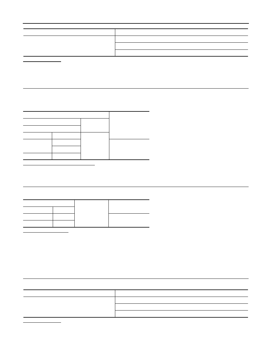
Signal name
Fuses and fusible link No.
Battery power supply
C
D
J
Terminals
Voltage
(Approx.)
(+)
(
−
)
IPDM E/R
Connector
Terminal
Ground
E9
1
Battery voltage
2
E10
8
IPDM E/R
Ground
Continuity
Connector
Terminal
E11
9
Existed
E12
19
Signal name
Fuses and fusible link No.
Battery power supply
C
D
J