Nissan Cube. Manual - part 677


  Index      Nissan     Nissan Cube (2014 year) - Service and Repair Manual


Search            


Content   ..  675  676  677  678   ..


Nissan Cube. Manual - part 677


MWI-32

< SYSTEM DESCRIPTION >

DIAGNOSIS SYSTEM (METER)

NOTE:

Some items are not available according to vehicle specification.

WARNING HISTORY

• Stores histories when warning/indicator lamp is turned on.
• “Warning History” indicates the “TIME” when the warning/indicator lamp is turned on.
• The “TIME” above is:
- 0: The condition that the warning/indicator lamp has been turned on 1 or more times after starting the engine

and waiting for 30 seconds.

- 1 - 39: The number of times the engine was restarted after the 0 condition.
- NO Warning History: Stores NO (0) turning on history of warning/indicator lamp.
NOTE:
• Warning History is not stored for approximately 30 seconds after the engine starts.
• Brake warning lamp does not store any history when the parking brake is applied or the brake fluid level gets

low.

Display Item

PKB SW
[On/Off]

Status of parking brake switch.

BUCKLE SW
[On/Off]

Status of seat belt buckle switch (driver side).

BRAKE OIL SW
[On/Off]

Status of brake fluid level switch.

A/C AMP CONN
[On/Off]

Status of A/C auto amp. connection recognition signal.

DISTANCE
[km]

Value of possible driving distance calculated by combination meter.

OUTSIDE TEMP
[

°

C or 

°

F]

Ambient air temperature value converted from ambient sensor signal received 
from ambient sensor.
NOTE:
This may not match with the temperature value indicated on the information dis-
play. (Because the information display value is a corrected value from the ambient 
sensor input value.)

FUEL LOW SIG
[On/Off]

Status of fuel level low warning signal to output to AV control unit via CAN com-
munication.

BUZZER 
[On/Off]

X

Buzzer status (in the combination meter) is detected from the buzzer output signal 
received from each unit via CAN communication and the warning output condition 
of the combination meter.

TPMS PRESS L
[On/Off]

Status of low tire pressure warning judged from low tire pressure warning lamp 
signal received from BCM with CAN communication line.
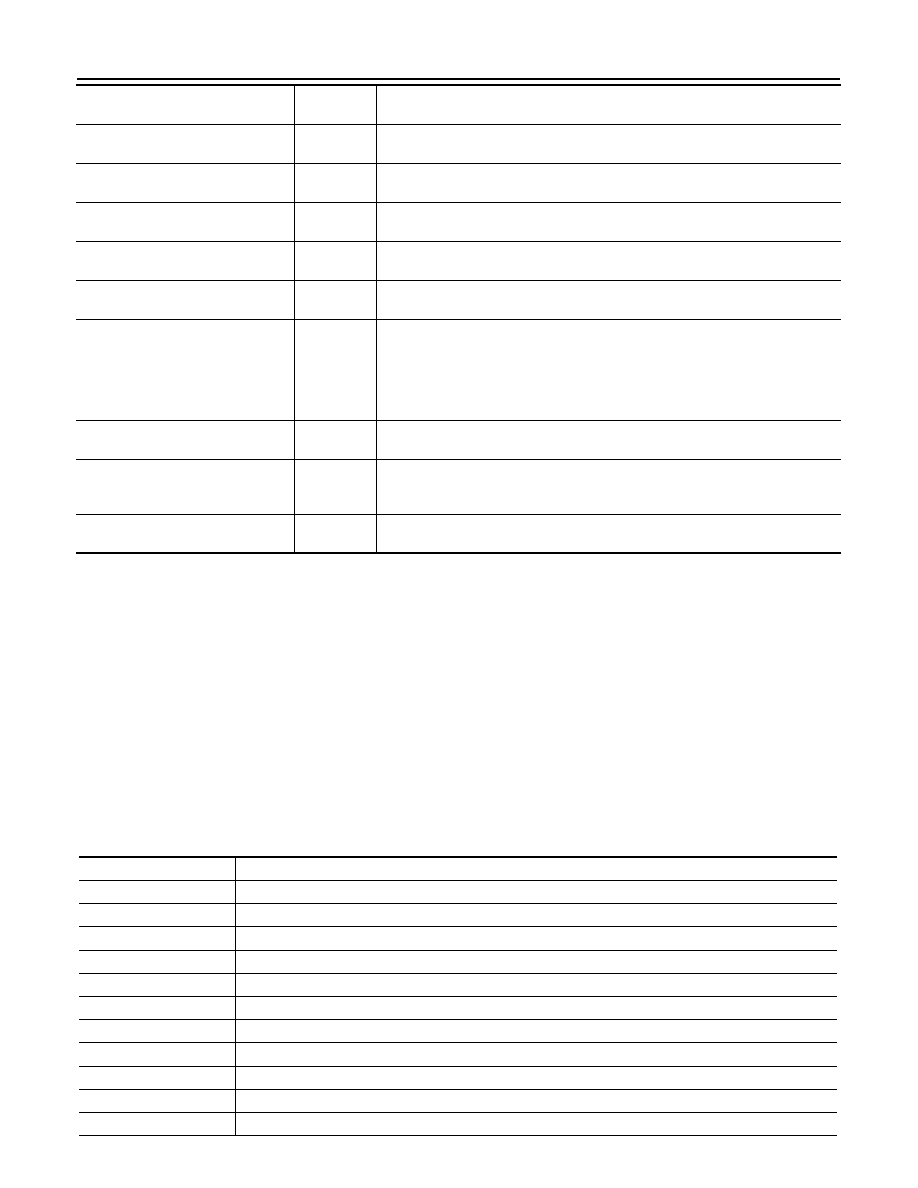
Display item [Unit]

MAIN

SIGNALS

Description

Display item

Description

ABS W/L

Lighting history of ABS warning lamp.

VDC/TCS IND

Lighting history of VDC OFF indicator lamp.

SLIP IND

Lighting history of VDC warning lamp.

BRAKE W/L

Lighting history of brake warning lamp.

DOOR W/L

Lighting history of door warning lamp.

OIL W/L

Lighting history of oil pressure warning lamp.

C-ENG W/L

Lighting history of malfunction indicator lamp.

CRUISE IND

Lighting history of CRUISE indicator lamp.

SPORT IND

Lighting history of OD OFF indicator lamp.

FUEL W/L

Lighting history of low fuel level warning lamp.

AIR PRES W/L

Lighting history of low tire pressure warning lamp.

MWI

DIAGNOSIS SYSTEM (METER)

MWI-33

< SYSTEM DESCRIPTION >

C

D

E

F

G

H

I

J

K

L

M

B

A

O

P

NOTE:
In items displayed on the CONSULT screen, only those listed in the above table are used.

KEY G/Y W/L

Lighting history of KEY warning lamp (G/Y).

EPS W/L

Lighting history of EPS warning lamp.

CHAGE W/L

Lighting history of charge warning lamp.

Display item

Description

MWI-34

< DTC/CIRCUIT DIAGNOSIS >

U1000 CAN COMM CIRCUIT

DTC/CIRCUIT DIAGNOSIS

U1000 CAN COMM CIRCUIT

Description

INFOID:0000000009945692

CAN (Controller Area Network) is a serial communication system for real time application. It is an on-vehicle
multiplex communication system with high data communication speed and excellent error detectability. Many
electronic control units are equipped onto vehicles, and each control unit shares information and links with
other control units during operation (not independent). In CAN communication, control units are connected
with two communication lines (CAN-H line, CAN-L line) allowing a high rate of information transmission with
less wiring. Each control unit transmits/receives data but selectively reads required data only.
CAN Communication Signal Chart. Refer to 

LAN-22, "CAN Communication Signal Chart"

.

DTC Logic

INFOID:0000000009945693

DTC DETECTION LOGIC

Diagnosis Procedure

INFOID:0000000009945694

1.

PERFORM SELF DIAGNOSTIC

1.

Turn ignition switch ON and wait for 2 seconds or more.

2.

Check “Self Diagnostic Result” of “METER/M&A”. 

Is “CAN COMM CIRCUIT” displayed?

YES

>> Refer to 

LAN-13, "Trouble Diagnosis Flow Chart"

.

NO

>> Refer to 

GI-40, "Intermittent Incident"

.

DTC

Display contents of 

CONSULT

Diagnostic item is detected when ...

Probable malfunction location

U1000

CAN COMM CIRCUIT

When combination meter is not transmitting or 
receiving CAN communication signal for 2 
seconds or more.

CAN communication system

MWI

U1010 CONTROL UNIT (CAN)

MWI-35

< DTC/CIRCUIT DIAGNOSIS >

C

D

E

F

G

H

I

J

K

L

M

B

A

O

P

U1010 CONTROL UNIT (CAN)

Description

INFOID:0000000009945695

Initial diagnosis of combination meter.

DTC Logic

INFOID:0000000009945696

DTC DETECTION LOGIC

Diagnosis Procedure

INFOID:0000000009945697

1.

REPLACE COMBINATION METER

When DTC “U1010” is detected, replace combination meter.

>> INSPECTION END

DTC

Display contents of CON-

SULT

Diagnostic item is detected when ...

Probable malfunction location

U1010

CONTROL UNIT (CAN)

If any malfunction is detected during initial di-
agnosis of combination meter CAN controller

Combination meter


Content   ..  675  676  677  678   ..