Nissan Cube. Manual - part 503


  Index      Nissan     Nissan Cube (2014 year) - Service and Repair Manual


Search            


Content   ..  501  502  503  504   ..


Nissan Cube. Manual - part 503


FSU-6

< PERIODIC MAINTENANCE >

FRONT SUSPENSION ASSEMBLY

PERIODIC MAINTENANCE

FRONT SUSPENSION ASSEMBLY

Inspection

INFOID:0000000009948818

COMPONENT PART

Check the mounting conditions (looseness, backlash) of each component and component conditions (wear,
damage) are normal.

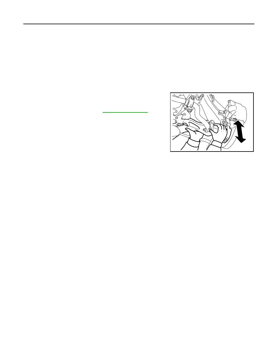
Ball Joint Axial End Play

1.

Set front wheels in a straight-ahead position.

2.

Move axle side of transverse link in the axial direction by hand.
Check there is no end play. 

CAUTION:

• Never depress brake pedal when measuring.
• Never perform with tires on level ground.
• Be careful not to damage ball joint boot. Never damage

the installation position by applying excessive force.

STRUT ASSEMBLY

Check for oil leakage, damage, and replace if necessary.

Axial end play

: Refer to 

FSU-19, "Ball Joint"

.

JSEIA0444ZZ

WHEEL ALIGNMENT

FSU-7

< PERIODIC MAINTENANCE >

C

D

F

G

H

I

J

K

L

M

A

B

FSU

N

O

P

WHEEL ALIGNMENT

Inspection

INFOID:0000000009948819

DESCRIPTION

CAUTION:

• Camber, caster, kingpin inclination angles cannot be adjusted.
• If camber, caster, or kingpin inclination angle is outside the standard, check front suspension parts

for wear and damage. Replace suspect parts if a malfunction is detected.

• Kingpin inclination angle is reference value, no inspection is required.
• Measure wheel alignment under unladen conditions. 
NOTE:
“Unladen conditions” means that fuel, engine coolant, and lubricant are full. Spare tire, jack, hand tools and
mats are in designated positions.

PRELIMINARY CHECK

Check the following:
• Tires for improper air pressure and wear. Refer to 

WT-54, "Tire Air Pressure"

.

• Road wheels for runout.
• Wheel bearing axial end play. Refer to 

FAX-7, "Inspection"

.

• Transverse link ball joint axial end play. Refer to 

FSU-6, "Inspection"

.

• Strut operation.
• Each mounting part of axle and suspension for looseness and deformation.
• Each of suspension member, strut assembly and transverse link for cracks, deformation and other damage.
• Vehicle height (posture).

GENERAL INFORMATION AND RECOMMENDATIONS

• A four-wheel thrust alignment should be performed.
- This type of alignment is recommended for any NISSAN/INFINITI vehicle.
- The four-wheel “thrust” process helps ensure that the vehicle is properly aligned and the steering wheel is

centered.

- The alignment rack itself should be capable of accepting any NISSAN/INFINITI vehicle.
- The rack should be checked to ensure that it is level.
• Check the machine is properly calibrated.
- Your alignment equipment should be regularly calibrated in order to give correct information.
- Check with the manufacturer of your specific equipment for their recommended Service/Calibration Sched-

ule.

ALIGNMENT PROCESS

IMPORTANT:
Use only the alignment specifications listed in this Service Manual.
• When displaying the alignment settings, many alignment machines use “indicators”: (Green/red, plus or

minus, Go/No Go). Never use these indicators.

- The alignment specifications programmed into your machine that operate these indicators may not be cor-

rect.

- This may result in an ERROR.
• Most camera-type alignment machines are equipped with both “Rolling Compensation” method and optional

“Jacking Compensation” method to “compensate” the alignment targets or head units. “Rolling Compensa-
tion” is the preferred method.

- If using the “Rolling Compensation” method, after installing the alignment targets or head units, push or pull

on the rear wheel to move the vehicle. Do not push or pull on the vehicle body.

- If using the “Jacking Compensation” method, after installing the alignment targets or head units, raise the

vehicle and rotate the wheels 1/2 turn both ways.
NOTE:
Do not use the “Rolling Compensation” method if you are using sensor-type alignment equipment.

- Follow all instructions for the alignment machine you're using for more information.

Adjustment

INFOID:0000000009948820

TOE-IN

• Loosen the steering outer socket, and then adjust the length using steering inner socket. 

FSU-8

< PERIODIC MAINTENANCE >

WHEEL ALIGNMENT

CAUTION:

• Always evenly adjust both toe-in alternately and adjust the difference between the left and right to

the standard. 

• Always fix the steering inner socket when tightening the steering outer socket. 

• After toe-in adjustment, adjust neutral position of steering angle sensor. Refer to 

BRC-9, "Special Repair

Requirement"

.

Toe-in

: Refer to 

FSU-19, "Wheel Alignment"

.

FRONT COIL SPRING AND STRUT

FSU-9

< REMOVAL AND INSTALLATION >

C

D

F

G

H

I

J

K

L

M

A

B

FSU

N

O

P

REMOVAL AND INSTALLATION

FRONT COIL SPRING AND STRUT

Exploded View

INFOID:0000000009948821

Removal and Installation

INFOID:0000000009948822

REMOVAL

1.

Remove tires with power tool. Refer to 

WT-46, "Exploded View"

.

2.

Remove lock plate. Refer to 

BR-20, "FRONT : Exploded View"

.

3.

Remove wheel sensor. Refer to 

BRC-110, "FRONT WHEEL SENSOR : Exploded View"

.

4.

Remove stabilizer connecting rod from strut assembly. Refer to 

FSU-15, "Exploded View"

.

5.

Remove strut assembly from steering knuckle.

6.

Remove cowl top cover rid (A).

7.

Remove mounting bolts of strut mounting insulator with power
tool, and then remove strut assembly.

INSTALLATION

Note the following, and install in the reverse order of removal.

1.

Strut

2.

Bound bumper

3.

Coil spring

4.

Strut mounting bearing

5.

Strut mounting insulator

6.

Piston rod lock nut

Refer to 

GI-4, "Components"

 for symbols in the figure.

JPEIA0178GB

JPEIA0189ZZ


Content   ..  501  502  503  504   ..