Nissan Cube. Manual - part 499
FUEL LEVEL SENSOR UNIT, FUEL FILTER AND FUEL PUMP ASSEMBLY
FL-5
< REMOVAL AND INSTALLATION >
C
D
E
F
G
H
I
J
K
L
M
A
FL
N
P
O
REMOVAL AND INSTALLATION
FUEL LEVEL SENSOR UNIT, FUEL FILTER AND FUEL PUMP ASSEMBLY
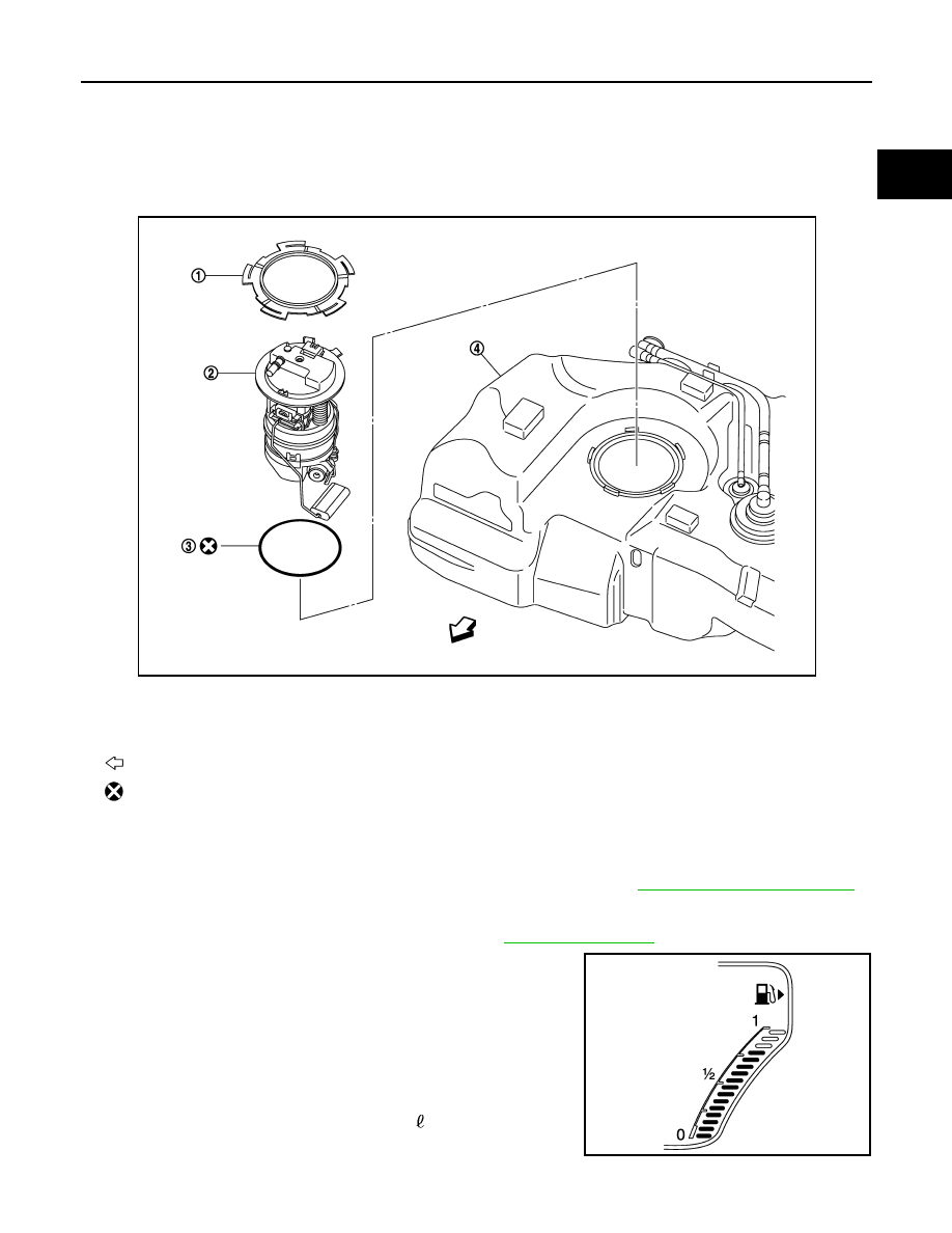
Exploded View
INFOID:0000000009950425
Removal and Installation
INFOID:0000000009950426
WARNING:
Read “General Precautions” when working on the fuel system. Refer to
.
REMOVAL
1.
Release the fuel pressure from the fuel lines. Refer to
2.
Check fuel level on fuel gauge. If fuel gauge indicates more than
the level as shown in the figure (full or almost full), drain fuel
from fuel tank until fuel gauge indicates level as shown in the fig-
ure or below.
NOTE:
The above instructions must be followed since fuel spills when
removing the fuel level sensor unit if the fuel level exceeds the
mounting surface.
• As a guide, fuel level becomes the position as shown in the
figure or below when approximately 10 (2-5/8 US gal, 2-1/4
Imp gal) of fuel are drained from fuel tank.
• In a case that fuel pump does not operate, perform the follow-
ing procedure.
1.
Lock ring
2.
Fuel level sensor unit, fuel filter and
fuel pump assembly
3.
O-ring
4.
Fuel tank
: Vehicle front
: Always replace after every disassembly.
JPBIA2907ZZ
JPBIA2797ZZ