Nissan Cube. Manual - part 399
 

  Index      Nissan     Nissan Cube (2014 year) - Service and Repair Manual


Search            


Content   ..  397  398  399  400   ..


Nissan Cube. Manual - part 399


EC-482

< SERVICE DATA AND SPECIFICATIONS (SDS) 

[MR18DE]

SERVICE DATA AND SPECIFICATIONS (SDS)

SERVICE DATA AND SPECIFICATIONS (SDS)

SERVICE DATA AND SPECIFICATIONS (SDS)

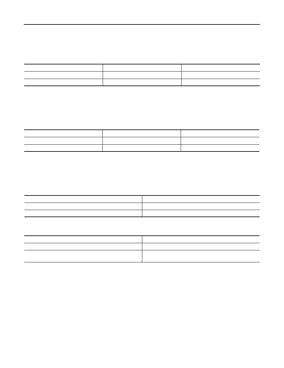
Idle Speed

INFOID:0000000009947593

*: Under the following conditions

• A/C switch: OFF

• Electric load: OFF (Lights, heater fan & rear window defogger)

• Steering wheel: Kept in straight-ahead position

Ignition Timing

INFOID:0000000009947594

*: Under the following conditions

• A/C switch: OFF

• Electric load: OFF (Lights, heater fan & rear window defogger)

• Steering wheel: Kept in straight-ahead position

Calculated Load Value

INFOID:0000000009947595

Mass Air Flow Sensor

INFOID:0000000009947596

*: Engine is warmed up to normal operating temperature and running under no load.

Transmission

Condition

Specification

CVT

No load* (in P or N position)

700 

±

 50 rpm

M/T

No load* (in Neutral position)

700 

±

 50 rpm

Transmission

Condition

Specification

CVT

No load* (in P or N position)

13 

±

 5

°

BTDC

M/T

No load* (in Neutral position)

13 

±

 5

°

BTDC

Condition

Specification (Using CONSULT or GST)

At idle

10 – 35 %

At 2,500 rpm

10 – 35 %

Supply voltage

Battery voltage (11 – 14 V)

Output voltage at idle

0.9 – 1.3V*

Mass air flow (Using CONSULT or GST)

1.0 – 4.0 g/sec at idle*

2.0 – 10.0 g/sec at 2,500 rpm*

EM-1

ENGINE

C

D

E

F

G

H

I

J

K

L

M

SECTION 

EM

A

EM

N

O

P

CONTENTS

ENGINE MECHANICAL

SYMPTOM DIAGNOSIS  ...............................

3

NOISE, VIBRATION AND HARSHNESS 
(NVH) TROUBLESHOOTING  .............................

3

NVH troubleshooting Chart  .......................................

3

PRECAUTION ...............................................

5

PRECAUTIONS ...................................................

5

Precautions for Removing of Battery Terminal  .........

5

Precaution for Procedure without Cowl Top Cover 

......

5

Precaution for Supplemental Restraint System 
(SRS) "AIR BAG" and "SEAT BELT PRE-TEN-
SIONER" .................................................................
..

5

Precautions For Engine Service ................................

6

Parts Requiring Angle Tightening  .............................

6

Liquid Gasket  ............................................................

7

PREPARATION ............................................

9

PREPARATION ...................................................

9

Special Service Tools ................................................

9

Commercial Service Tools  ......................................

10

PERIODIC MAINTENANCE .........................

13

DRIVE BELT .......................................................

13

Exploded View  ........................................................

13

Checking .................................................................

13

Tension Adjustment  ................................................

13

Removal and Installation .........................................

13

AIR CLEANER FILTER ......................................

15

Removal and Installation .........................................

15

Inspection (Viscous Paper Type)  ............................

15

SPARK PLUG  ....................................................

16

Exploded View  ........................................................

16

Removal and Installation .........................................

16

Inspection ................................................................

17

CAMSHAFT VALVE CLEARANCE  ...................

18

Inspection and Adjustment  ......................................

18

COMPRESSION PRESSURE  ...........................

21

Inspection ................................................................

21

REMOVAL AND INSTALLATION  ...............

22

ENGINE COVER  ...............................................

22

Exploded View .........................................................

22

Removal and Installation  .........................................

22

DRIVE BELT AUTO TENSIONER AND IDLER 
PULLEY .............................................................

23

Exploded View .........................................................

23

Removal and Installation  .........................................

23

AIR CLEANER AND AIR DUCT  .......................

24

Exploded View .........................................................

24

Removal and Installation  .........................................

24

Inspection ................................................................

25

INTAKE MANIFOLD  .........................................

26

Exploded View .........................................................

26

Removal and Installation  .........................................

26

EXHAUST MANIFOLD ......................................

29

Exploded View .........................................................

29

Removal and Installation  .........................................

29

Inspection ................................................................

31

OIL PAN (LOWER)  ...........................................

32

Exploded View .........................................................

32

Removal and Installation  .........................................

32

Inspection ................................................................

34

FUEL INJECTOR AND FUEL TUBE  ................

35

Exploded View .........................................................

35

Removal and Installation  .........................................

35

Inspection ................................................................

38

IGNITION COIL, SPARK PLUG AND ROCK-
ER COVER  ........................................................

40

Exploded View .........................................................

40

EM-2

Removal and Installation  ........................................

40

TIMING CHAIN  ..................................................

42

Exploded View  ........................................................

42

Removal and Installation  ........................................

43

Inspection ...............................................................

51

CAMSHAFT .......................................................

53

Exploded View  ........................................................

53

Removal and Installation  ........................................

54

Inspection ...............................................................

57

OIL SEAL ...........................................................

62

VALVE OIL SEAL  .....................................................

62

VALVE OIL SEAL : Removal and Installation .........

62

FRONT OIL SEAL .....................................................

62

FRONT OIL SEAL : Removal and Installation  ........

63

REAR OIL SEAL  .......................................................

63

REAR OIL SEAL : Removal and Installation  ..........

63

CYLINDER HEAD  ..............................................

65

Exploded View  ........................................................

65

Removal and Installation  ........................................

66

Disassembly and Assembly ....................................

67

Inspection ...............................................................

71

UNIT REMOVAL AND INSTALLATION .....

74

ENGINE ASSEMBLY .........................................

74

Exploded View  ........................................................

74

Removal and Installation  ........................................

74

Inspection ...............................................................

78

UNIT DISASSEMBLY AND ASSEMBLY ....

79

ENGINE STAND SETTING  ...............................

79

Setting .....................................................................

79

ENGINE UNIT  ....................................................

81

Disassembly ............................................................

81

Assembly ................................................................

81

OIL PAN (UPPER) .............................................

82

Exploded View  ........................................................

82

Removal and Installation .........................................

82

Inspection ................................................................

85

CYLINDER BLOCK  ...........................................

86

Exploded View  ........................................................

86

Disassembly and Assembly  ....................................

87

Inspection ................................................................

95

HOW TO SELECT PISTON AND BEARING  ...

106

Description ............................................................

106

Piston ....................................................................

106

Connecting Rod Bearing .....................................

107

Main Bearing ........................................................

109

SERVICE DATA AND SPECIFICATIONS 
(SDS) .........................................................

113

SERVICE DATA AND SPECIFICATIONS 
(SDS) ................................................................

113

General Specification ............................................

113

Drive Belt  ..............................................................

113

Spark Plug  ............................................................

113

Exhaust Manifold  ..................................................

114

Camshaft ...............................................................

114

Cylinder Head  .......................................................

116

Cylinder Block  .......................................................

118

Connecting Rod Bearing .......................................

122

Main Bearing .........................................................

122

NOISE, VIBRATION AND HARSHNESS (NVH) TROUBLESHOOTING

EM-3

< SYMPTOM DIAGNOSIS >

C

D

E

F

G

H

I

J

K

L

M

A

EM

N

P

O

SYMPTOM DIAGNOSIS

NOISE, VIBRATION AND HARSHNESS (NVH) TROUBLESHOOTING

NVH troubleshooting Chart

INFOID:0000000009944906

1.

Locate the area where noise occurs.

2.

Confirm the type of noise.

3.

Specify the operating condition of engine.

PBIC3932E


Content   ..  397  398  399  400   ..