Nissan Cube. Manual - part 379


  Index      Nissan     Nissan Cube (2014 year) - Service and Repair Manual


Search            


Content   ..  377  378  379  380   ..


Nissan Cube. Manual - part 379


EC-402

< DTC/CIRCUIT DIAGNOSIS >

[MR18DE]

COOLING FAN

COOLING FAN

Description

INFOID:0000000009947544

The ECM controls the cooling fan corresponding to the vehicle speed, engine coolant temperature, refrigerant
pressure, and air conditioner ON signal. The control system has 3-step control [HIGH/LOW/OFF].

COOLING FAN MOTOR

Models without A/C

The cooling fan operates at each speed when the current flows in the cooling fan motor as per the following.

Models with A/C

The cooling fan operates at high (HI) speed when the current flows, and operates at low (LOW) speed when
cooling fan motor and the resistor are circuited in series.

Component Function Check

INFOID:0000000009947545

1.

CHECK COOLING FAN FUNCTION

With CONSULT

1.

Turn ignition switch ON.

2.

Perform “COOLING FAN” in “ACTIVE TEST” mode with CONSULT.

3.

Touch “LOW” and “Hi” on the CONSULT screen.

4.

Check that cooling fan operates at each speed.

Without CONSULT

1.

Perform IPDM E/R auto active test and check cooling fan motor operation. Refer to 

PCS-10, "Diagnosis

Description"

 or 

PCS-41, "Diagnosis Description"

.

2.

Check that cooling fan operates at each speed.

Is the inspection result normal?

YES

>> INSPECTION END

NO

>> Refer to 

EC-402, "Diagnosis Procedure"

.

Diagnosis Procedure

INFOID:0000000009947546

1.

CHECK GROUND CONNECTION

1.

Turn ignition switch OFF.

2.

Check ground connection E21. Refer to Ground Inspection in 

GI-43, "Circuit Inspection"

.

Is the inspection result normal?

YES

>> GO TO 2.

NO

>> Repair or replace ground connection.

2.

CHECK COOLING FAN MOTOR CIRCUIT

1.

Disconnect cooling fan motor harness connector.

2.

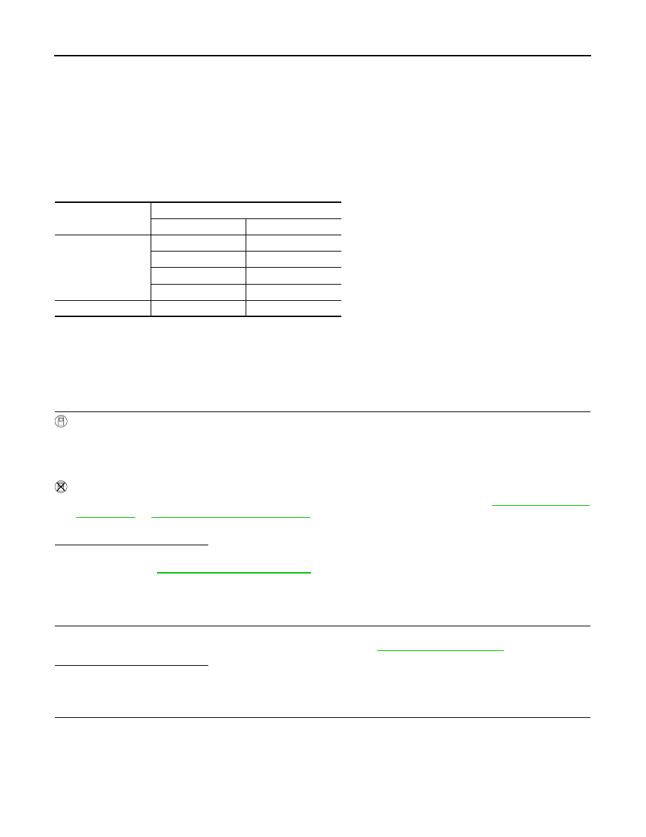
Check the continuity between IPDM E/R harness connector and cooling fan motor harness connector.

Cooling fan Speed

Cooling fan motor terminals

(+)

(–)

Low (LOW)

1

3 and 4

2

3 and 4

1 and 2

3

1 and 2

4

High (HI)

1 and 2

3 and 4

COOLING FAN

EC-403

< DTC/CIRCUIT DIAGNOSIS >

[MR18DE]

C

D

E

F

G

H

I

J

K

L

M

A

EC

N

P

O

3.

Check the continuity between cooling fan motor harness connector and ground.

4.

Also check harness for short to ground and short to power.

OK or NG

OK

>> GO TO 4.

NG

>> GO TO 3.

3.

DETECT MALFUNCTIONING PART

Check the following.
• Harness for open or short between cooling fan motor and IPDM E/R
• Harness for open or short between cooling fan motor and ground

>> Repair open circuit or short to ground or short to power in harness or connectors.

4.

CHECK COOLING FAN MOTOR

Refer to 

EC-403, "Component Inspection"

.

OK or NG

OK

>> GO TO 5.

NG

>> Replace cooling fan motor. Refer to 

CO-17, "Exploded View"

.

5.

CHECK INTERMITTENT INCIDENT

Perfor

GI-40, "Intermittent Incident"

.

OK or NG

OK

>> Replace IPDM E/R. Refer to 

PCS-34, "Removal and Installation"

 (With I-KEY) or 

PCS-64,

"Removal and Installation"

 (Without I-KEY).

NG 

>> Repair or replace harness or connector.

Component Inspection

INFOID:0000000009947547

COOLING FAN MOTOR

1.

Disconnect cooling fan motor harness connectors.

2.

Supply cooling fan motor terminals with battery voltage and check operation.

Cooling fan motor should operate.
If NG, replace cooling fan motor. Refer to 

CO-17, "Exploded View"

.

IPDM E/R

Cooling fan motor

Continuity

Connector

Terminal

Connector

Terminal

E10

5

E62

1

Existed

7

2

E11

10

3

Cooling fan motor

Ground

Continuity

Connector

Terminal

E62

4

Ground

Existed

Speed

terminals

(+)

(

)

Cooling fan mo-
tor

Low 

1

4

2

3

High

1 and 2

3 and 4

EC-404

< DTC/CIRCUIT DIAGNOSIS >

[MR18DE]

ELECTRICAL LOAD SIGNAL

ELECTRICAL LOAD SIGNAL

Description

INFOID:0000000009947548

The electrical load signal (Headlamp switch signal, rear window defogger switch signal, etc.) is transferred via
the CAN communication line.

Component Function Check

INFOID:0000000009947549

1.

CHECK REAR WINDOW DEFOGGER SWITCH FUNCTION

1.

Turn ignition switch ON.

2.

Connect CONSULT and select “DATA MONITOR” mode.

3.

Select “LOAD SIGNAL” and check indication under the following conditions.

Is the inspection result normal?

YES

>> GO TO 2.

NO

>> Go to 

EC-404, "Diagnosis Procedure"

.

2.

CHECK LIGHTING SWITCH FUNCTION

Check “LOAD SIGNAL” indication under the following conditions.

Is the inspection result normal?

YES

>> GO TO 3.

NO

>> Go to 

EC-404, "Diagnosis Procedure"

.

3.

CHECK HEATER FAN CONTROL SWITCH FUNCTION

Select “HEATER FAN SW” and check indication under the following conditions.

Is the inspection result normal?

YES

>> INSPECTION END

NO

>> Go to 

EC-404, "Diagnosis Procedure"

.

Diagnosis Procedure

INFOID:0000000009947550

1.

INSPECTION START

Confirm the malfunctioning circuit (rear window defogger, headlamp or heater fan). Refer to 

EC-404, "Compo-

nent Function Check"

.

Which circuit is related to the incident?

Rear window defogger>>GO TO 2.
Headlamp>>GO TO 3.
Heater fan>>GO TO 4.

2.

CHECK REAR WINDOW DEFOGGER SYSTEM

Refer to 

DEF-3, "Work Flow"

.

Monitor item

Condition

Indication

LOAD SIGNAL

Rear window defogger switch

ON

ON

OFF

OFF

Monitor item

Condition

Indication

LOAD SIGNAL

Lighting switch

ON at 2nd posi-
tion

ON

OFF

OFF

Monitor item

Condition

Indication

HEATER FAN 
SW

Heater fan control switch

ON

ON

OFF

OFF

ELECTRICAL LOAD SIGNAL

EC-405

< DTC/CIRCUIT DIAGNOSIS >

[MR18DE]

C

D

E

F

G

H

I

J

K

L

M

A

EC

N

P

O

>> INSPECTION END

3.

CHECK HEADLAMP SYSTEM

Refer to 

EXL-4, "Work Flow"

.

>> INSPECTION END

4.

CHECK HEATER FAN CONTROL SYSTEM

Refer to 

HA-3, "Work Flow"

.

>> INSPECTION END


Content   ..  377  378  379  380   ..