Nissan Cube. Manual - part 377


  Index      Nissan     Nissan Cube (2014 year) - Service and Repair Manual


Search            


Content   ..  375  376  377  378   ..


Nissan Cube. Manual - part 377


EC-394

< DTC/CIRCUIT DIAGNOSIS >

[MR18DE]

P2138 APP SENSOR

Diagnosis Procedure

INFOID:0000000009947533

1.

CHECK GROUND CONNECTION

1.

Turn ignition switch OFF.

2.

Check ground connection E38. Refer to 

GI-43, "Circuit Inspection"

.

Is the inspection result normal?

YES

>> GO TO 2.

NO

>> Repair or replace ground connection.

2.

CHECK APP SENSOR 1 POWER SUPPLY CIRCUIT

1.

Disconnect accelerator pedal position (APP) sensor harness connector.

2.

Turn ignition switch ON.

3.

Check the voltage between APP sensor harness connector and ground.

Is the inspection result normal?

YES

>> GO TO 3.

NO

>> Repair open circuit or short to ground or shot to power in harness or connectors.

3.

CHECK APP SENSOR 2 POWER SUPPLY CIRCUIT-I

1.

Check the voltage between APP sensor harness connector and ground.

Is the inspection result normal?

YES

>> GO TO 7.

NO

>> GO TO 4.

4.

CHECK APP SENSOR 2 POWER SUPPLY CIRCUIT-II

1.

Turn ignition switch OFF.

2.

Disconnect ECM harness connector.

3.

Check the continuity between APP sensor harness connector and ECM harness connector.

Is the inspection result normal?

YES

>> GO TO 5.

NO

>> Repair open circuit or short to ground or shot to power in harness or connectors.

5.

CHECK SENSOR POWER SUPPLY CIRCUIT

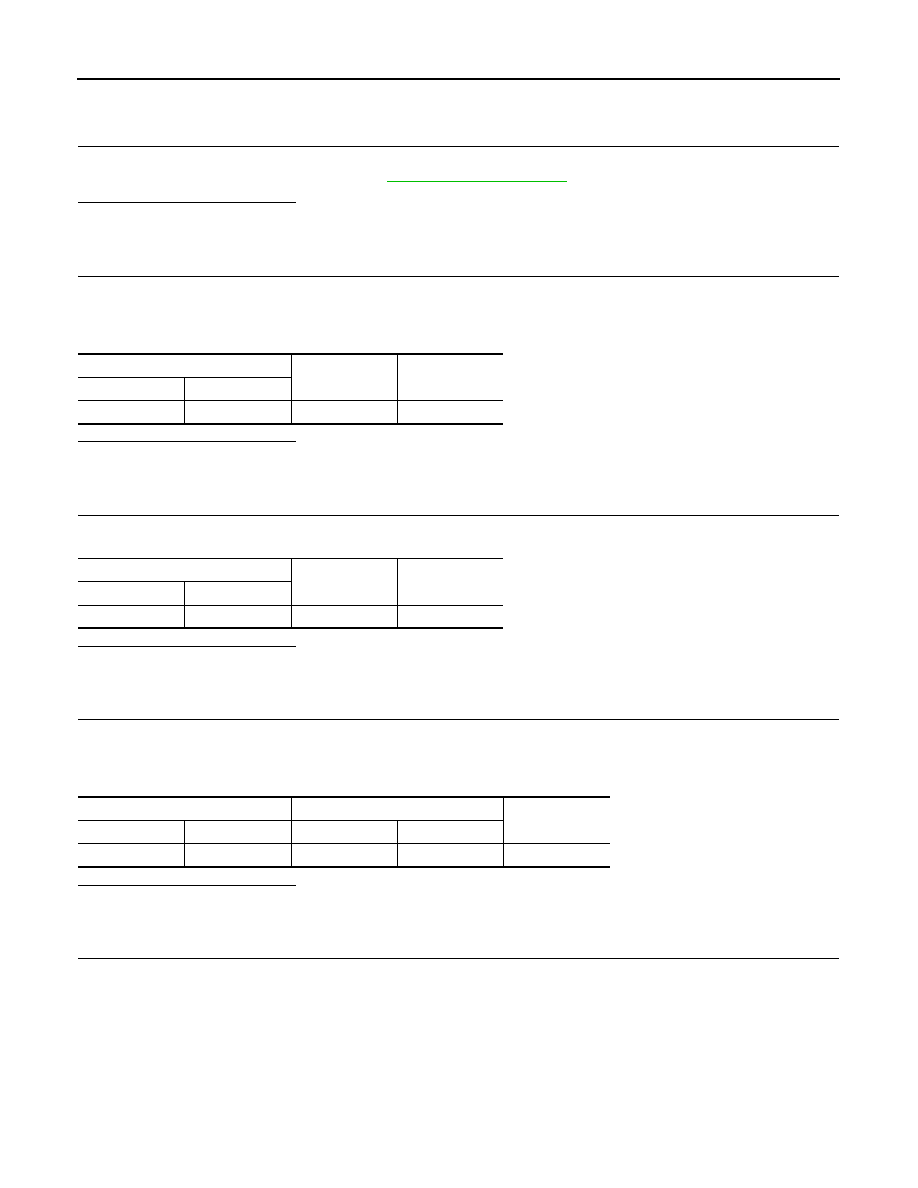
Check harness for short to power and short to ground, between the following terminals.

APP sensor

Ground

Voltage

Connector

Terminal

E110

4

Ground

Approx. 5 V

APP sensor

Ground

Voltage

Connector

Terminal

E110

5

Ground

Approx. 5 V

APP sensor

ECM

Continuity

Connector

Terminal

Connector

Terminal

E110

4

E16

106

Existed

P2138 APP SENSOR

EC-395

< DTC/CIRCUIT DIAGNOSIS >

[MR18DE]

C

D

E

F

G

H

I

J

K

L

M

A

EC

N

P

O

Is the inspection result normal?

YES

>> GO TO 6.

NO

>> Repair short to ground or short to power in harness or connectors.

6.

CHECK COMPONENTS

Check the following.
• Crankshaft position sensor (POS) (Refer to 

EC-244, "Component Inspection"

.)

• EVAP control system pressure sensor (Refer to 

EC-279, "Component Inspection"

.)

• Refrigerant pressure sensor (Refer to 

EC-425, "Diagnosis Procedure"

.)

Is the inspection result normal?

YES

>> GO TO 11.

NO

>> Replace malfunctioning component.

7.

CHECK APP SENSOR GROUND CIRCUIT FOR OPEN AND SHORT

1.

Turn ignition switch OFF.

2.

Disconnect ECM harness connector.

3.

Check the continuity between APP sensor harness connector and ECM harness connector as per the fol-
lowing.

4.

Also check harness for short to ground and short to power.

Is the inspection result normal?

YES

>> GO TO 8.

NO

>> Repair open circuit or short to ground or shot to power in harness or connectors.

8.

CHECK APP SENSOR INPUT SIGNAL CIRCUIT FOR OPEN AND SHORT

1.

Check the continuity between APP sensor harness connector and ECM harness connector as per the fol-
lowing.

2.

Also check harness for short to ground and short to power.

Is the inspection result normal?

YES

>> GO TO 9.

NO

>> Repair open circuit or short to ground or shot to power in harness or connectors.

9.

CHECK APP SENSOR

Refer to 

EC-396, "Component Inspection"

.

Is the inspection result normal?

ECM

Sensor

Connector

Terminal

Name

Connector

Terminal

F8

74

Refrigerant pressure sensor

E17

3

75

CKP sensor (POS)

F15

1

76

EVAP control system pressure sen-
sor

B104

3

77

Battery current sensor

F53

1

E16

102

APP sensor

E12

5

APP sensor

ECM

Continuity

Connector

Terminal

Connector

Terminal

E110

2

E16

111

Existed

1

104

APP sensor

ECM

Continuity

Connector

Terminal

Connector

Terminal

E110

3

E16

110

Existed

6

103

EC-396

< DTC/CIRCUIT DIAGNOSIS >

[MR18DE]

P2138 APP SENSOR

YES

>> GO TO 11.

NO

>> GO TO 10.

10.

REPLACE ACCELERATOR PEDAL ASSEMBLY

1.

Replace accelerator pedal assembly.

2.

Perform 

EC-396, "Special Repair Requirement"

.

>> INSPECTION END

11.

CHECK INTERMITTENT INCIDENT

Refer to 

GI-40, "Intermittent Incident"

.

>> INSPECTION END

Component Inspection

INFOID:0000000009947534

1.

CHECK ACCELERATOR PEDAL POSITION SENSOR

1.

Reconnect all harness connectors disconnected.

2.

Turn ignition switch ON.

3.

Check the voltage between ECM harness connector and ground.

Is the inspection result normal?

YES

>> INSPECTION END

NO

>> GO TO 2.

2.

REPLACE ACCELERATOR PEDAL ASSEMBLY

1.

Replace accelerator pedal assembly.

2.

Perform 

EC-396, "Special Repair Requirement"

.

>> INSPECTION END

Special Repair Requirement

INFOID:0000000009947535

1.

PERFORM ACCELERATOR PEDAL RELEASED POSITION LEARNING

Refer to 

EC-19, "ACCELERATOR PEDAL RELEASED POSITION LEARNING : Special Repair Requirement"

.

>> GO TO 2.

2.

PERFORM THROTTLE VALVE CLOSED POSITION LEARNING

Refer to 

EC-19, "THROTTLE VALVE CLOSED POSITION LEARNING : Special Repair Requirement"

.

>> GO TO 3.

3.

PERFORM IDLE AIR VOLUME LEARNING

Refer to 

EC-20, "IDLE AIR VOLUME LEARNING : Special Repair Requirement"

.

>> END

ECM

Ground

Condition

Voltage

Connector

Terminal

E16

110

(APP sensor 1 

signal)

Ground

Accelerator ped-
al

Fully released

0.6 - 0.9 V

Fully depressed

3.9 - 4.7 V

103

(APP sensor 2 

signal)

Fully released

0.3 - 0.6 V

Fully depressed

1.95 - 2.4 V

ASCD BRAKE SWITCH

EC-397

< DTC/CIRCUIT DIAGNOSIS >

[MR18DE]

C

D

E

F

G

H

I

J

K

L

M

A

EC

N

P

O

ASCD BRAKE SWITCH

Description

INFOID:0000000009947536

When the brake pedal is depressed, ASCD brake switch is turned OFF and stop lamp switch is turned ON.
ECM detects the state of the brake pedal by this input of two kinds (ON/OFF signal).
Refer to 

EC-65, "System Description"

 for the ASCD function.

Component Function Check

INFOID:0000000009947537

1.

CHECK FOR ASCD BRAKE SWITCH FUNCTION

 With CONSULT

1.

Turn ignition switch ON.

2.

Select “BRAKE SW1” in “DATA MONITOR” mode with CONSULT.

3.

Check “BRAKE SW1” indication under the following conditions.

 Without CONSULT

1.

Turn ignition switch ON.

2.

Check the voltage between ECM harness connector terminals.

Is the inspection result normal?

YES

>> INSPECTION END

NO

>> Go to 

EC-397, "Diagnosis Procedure"

.

Diagnosis Procedure

INFOID:0000000009947538

1.

CHECK ASCD BRAKE SWITCH POWER SUPPLY CIRCUIT-I

1.

Turn ignition switch OFF.

2.

Disconnect ASCD brake switch harness connector.

3.

Turn ignition switch ON.

4.

Check the voltage between ASCD brake switch harness connector and ground.

Is the inspection result normal?

YES

>> GO TO 7.

NO-1

>> CVT models: GO TO 2.

NO-2

>> M/T models: GO TO 3.

2.

DETECT MALFUNCTIONING PART

Check the following.
• Harness connectors E105, M77

Monitor item

Condition

Indication

BRAKE SW1

Brake pedal (CVT)
Brake pedal and clutch pedal (M/T)

Slightly de-
pressed

OFF

Fully released

ON

ECM

Condition

Voltage

Connector

+

-

Terminal

Terminal

E16

100

(ASCD brake 

switch signal)

108

Brake pedal (CVT)
Brake pedal and clutch pedal (M/T)

Slightly de-
pressed

Approx. 0 V

Fully released

Battery voltage

ASCD brake switch

Ground

Voltage

Connector

Terminal

E112

1

Ground

Battery voltage


Content   ..  375  376  377  378   ..