Nissan Cube. Manual - part 375


  Index      Nissan     Nissan Cube (2014 year) - Service and Repair Manual


Search            


Content   ..  373  374  375  376   ..


Nissan Cube. Manual - part 375


EC-386

< DTC/CIRCUIT DIAGNOSIS >

[MR18DE]

P2127, P2128 APP SENSOR

P2127, P2128 APP SENSOR

Description

INFOID:0000000009947521

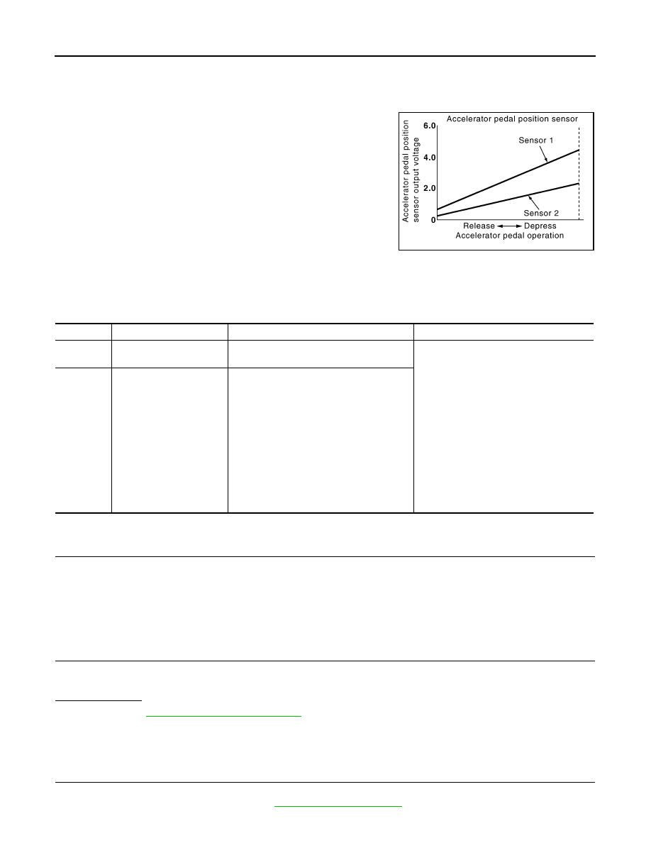
The accelerator pedal position sensor is installed on the upper end
of the accelerator pedal assembly. The sensor detects the accelera-
tor position and sends a signal to the ECM.
Accelerator pedal position sensor has two sensors. These sensors
are a kind of potentiometer which transform the accelerator pedal
position into output voltage, and emit the voltage signal to the ECM.
The ECM judges the current opening angle of the accelerator pedal
from these signals and controls the throttle control motor based on
these signals.
Idle position of the accelerator pedal is determined by the ECM
receiving the signal from the accelerator pedal position sensor. The
ECM uses this signal for the engine operation such as fuel cut.

DTC Logic

INFOID:0000000009947522

DTC DETECTION LOGIC

DTC CONFIRMATION PROCEDURE

1.

PRECONDITIONING

If DTC Confirmation Procedure has been previously conducted, always turn ignition switch OFF and wait at
least 10 seconds before conducting the next test.
TESTING CONDITION:
Before performing the following procedure, confirm that battery voltage is more than 8 V at idle.

>> GO TO 2.

2.

PERFORM DTC CONFIRMATION PROCEDURE

1.

Start engine and let it idle for 1 second.

2.

Check DTC.

Is DTC detected?

YES

>> Go to 

EC-386, "Diagnosis Procedure"

.

NO

>> INSPECTION END

Diagnosis Procedure

INFOID:0000000009947523

1.

CHECK GROUND CONNECTION

1.

Turn ignition switch OFF.

2.

Check ground connection E38. Refer to 

GI-43, "Circuit Inspection"

.

PBIB1741E

DTC No.

Trouble diagnosis name

DTC detecting condition

Possible cause

P2127

Accelerator pedal position 
sensor 2 circuit low input

An excessively low voltage from the APP 
sensor 2 is sent to ECM.

• Harness or connectors

(APP sensor 2 circuit is open or shorted.)
[Crankshaft position sensor (POS) circuit 
is shorted.]
(Refrigerant pressure sensor circuit is 
shorted.)
(EVAP control system pressure sensor 
circuit is shorted.)
(Battery current sensor circuit is shorted.)

• Accelerator pedal position sensor

(APP sensor 2)

• Crankshaft position sensor (POS)
• Refrigerant pressure sensor
• EVAP control system pressure sensor
• Battery current sensor

P2128

Accelerator pedal position 
sensor 2 circuit high input

An excessively high voltage from the APP 
sensor 2 is sent to ECM.

P2127, P2128 APP SENSOR

EC-387

< DTC/CIRCUIT DIAGNOSIS >

[MR18DE]

C

D

E

F

G

H

I

J

K

L

M

A

EC

N

P

O

Is the inspection result normal?

YES

>> GO TO 2.

NO

>> Repair or replace ground connection.

2.

CHECK APP SENSOR 2 POWER SUPPLY CIRCUIT-I

1.

Disconnect accelerator pedal position (APP) sensor harness connector.

2.

Turn ignition switch ON.

3.

Check the voltage between APP sensor harness connector and ground.

Is the inspection result normal?

YES

>> GO TO 6.

NO

>> GO TO 3.

3.

CHECK APP SENSOR 2 POWER SUPPLY CIRCUIT-II

1.

Turn ignition switch OFF.

2.

Disconnect ECM harness connector.

3.

Check the continuity between APP sensor harness connector and ECM harness connector.

Is the inspection result normal?

YES

>> GO TO 4.

NO

>> Repair open circuit or short to ground or short to power in harness or connectors.

4.

CHECK SENSOR POWER SUPPLY CIRCUIT

Check harness for short to power and short to ground, between the following terminals.

Is the inspection result normal?

YES

>> GO TO 5.

NO

>> Repair short to ground or short to power in harness or connectors.

5.

CHECK COMPONENTS

Check the following.
• Crankshaft position sensor (POS) (Refer to 

EC-244, "Component Inspection"

.)

• EVAP control system pressure sensor (Refer to 

EC-279, "Component Inspection"

.)

• Refrigerant pressure sensor (Refer to 

EC-425, "Diagnosis Procedure"

.)

Is the inspection result normal?

YES

>> GO TO 10.

NO

>> Replace malfunctioning component.

6.

CHECK APP SENSOR 2 GROUND CIRCUIT FOR OPEN AND SHORT

1.

Turn ignition switch OFF.

APP sensor

Ground

Voltage

Connector

Terminal

E110

5

Ground

Approx. 5 V

APP sensor

ECM

Continuity

Connector

Terminal

Connector

Terminal

E110

5

E16

102

Existed

ECM

Sensor

Connector

Terminal

Name

Connector

Terminal

F8

74

Refrigerant pressure sensor

E17

3

75

CKP sensor (POS)

F15

1

76

EVAP control system pressure sen-
sor

B104

3

77

Battery current sensor

F53

1

E16

102

APP sensor

E12

5

EC-388

< DTC/CIRCUIT DIAGNOSIS >

[MR18DE]

P2127, P2128 APP SENSOR

2.

Disconnect ECM harness connector.

3.

Check the continuity between APP sensor harness connector and ECM harness connector.

4.

Also check harness for short to ground and short to power.

Is the inspection result normal?

YES

>> GO TO 7.

NO

>> Repair open circuit or short to ground or short to power in harness or connectors.

7.

CHECK APP SENSOR 2 INPUT SIGNAL CIRCUIT FOR OPEN AND SHORT

1.

Check the continuity between APP sensor harness connector and ECM harness connector.

2.

Also check harness for short to ground and short to power.

Is the inspection result normal?

YES

>> GO TO 8.

NO

>> Repair open circuit or short to ground or short to power in harness or connectors.

8.

CHECK APP SENSOR

Refer to 

EC-388, "Component Inspection"

.

Is the inspection result normal?

YES

>> GO TO 10.

NO

>> GO TO 9.

9.

REPLACE ACCELERATOR PEDAL ASSEMBLY

1.

Replace accelerator pedal assembly.

2.

Perform 

EC-389, "Special Repair Requirement"

.

>> INSPECTION END

10.

CHECK INTERMITTENT INCIDENT

Refer to 

GI-40, "Intermittent Incident"

.

>> INSPECTION END

Component Inspection

INFOID:0000000009947524

1.

CHECK ACCELERATOR PEDAL POSITION SENSOR

1.

Reconnect all harness connectors disconnected.

2.

Turn ignition switch ON.

3.

Check the voltage between ECM harness connector and ground.

APP sensor

ECM

Continuity

Connector

Terminal

Connector

Terminal

E110

1

E16

104

Existed

APP sensor

ECM

Continuity

Connector

Terminal

Connector

Terminal

E110

6

E16

103

Existed

ECM

Ground

Condition

Voltage

Connector

Terminal

E16

110

(APP sensor 1 

signal)

Ground

Accelerator ped-
al

Fully released

0.6 - 0.9 V

Fully depressed

3.9 - 4.7 V

103

(APP sensor 2 

signal)

Fully released

0.3 - 0.6 V

Fully depressed

1.95 - 2.4 V

P2127, P2128 APP SENSOR

EC-389

< DTC/CIRCUIT DIAGNOSIS >

[MR18DE]

C

D

E

F

G

H

I

J

K

L

M

A

EC

N

P

O

Is the inspection result normal?

YES

>> INSPECTION END

NO

>> GO TO 2.

2.

REPLACE ACCELERATOR PEDAL ASSEMBLY

1.

Replace accelerator pedal assembly.

2.

Perform 

EC-396, "Special Repair Requirement"

.

>> INSPECTION END

Special Repair Requirement

INFOID:0000000009947525

1.

PERFORM ACCELERATOR PEDAL RELEASED POSITION LEARNING

Refer to 

EC-19, "ACCELERATOR PEDAL RELEASED POSITION LEARNING : Special Repair Requirement"

.

>> GO TO 2.

2.

PERFORM THROTTLE VALVE CLOSED POSITION LEARNING

Refer to 

EC-19, "THROTTLE VALVE CLOSED POSITION LEARNING : Special Repair Requirement"

.

>> GO TO 3.

3.

PERFORM IDLE AIR VOLUME LEARNING

Refer to 

EC-20, "IDLE AIR VOLUME LEARNING : Special Repair Requirement"

.

>> END


Content   ..  373  374  375  376   ..