Nissan Cube. Manual - part 374


  Index      Nissan     Nissan Cube (2014 year) - Service and Repair Manual


Search            


Content   ..  372  373  374  375   ..


Nissan Cube. Manual - part 374


EC-382

< DTC/CIRCUIT DIAGNOSIS >

[MR18DE]

P2119 ELECTRIC THROTTLE CONTROL ACTUATOR

3.

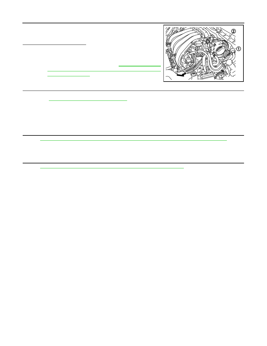
Check if foreign matter is caught between the throttle valve (1)
and the housing.

-

Electric throttle control actuator (2)

Is the inspection result normal?

YES

>> GO TO 2.

NO

>> Remove the foreign matter and clean the electric throttle

control actuator inside, and then perform throttle valve
closed position learning. Refer to 

EC-19, "THROTTLE

VALVE CLOSED POSITION LEARNING : Special
Repair Requirement"

.

2.

REPLACE ELECTRIC THROTTLE CONTROL ACTUATOR

1.

Replace electric throttle control actuator.

2.

Perform 

EC-382, "Special Repair Requirement"

.

>> INSPECTION END

Special Repair Requirement

INFOID:0000000009947515

1.

PERFORM THROTTLE VALVE CLOSED POSITION LEARNING

Refer to 

EC-19, "THROTTLE VALVE CLOSED POSITION LEARNING : Special Repair Requirement"

.

>> GO TO 2.

2.

PERFORM IDLE AIR VOLUME LEARNING

Refer to 

EC-20, "IDLE AIR VOLUME LEARNING : Special Repair Requirement"

.

>> END

JMBIA2312ZZ

P2122, P2123 APP SENSOR

EC-383

< DTC/CIRCUIT DIAGNOSIS >

[MR18DE]

C

D

E

F

G

H

I

J

K

L

M

A

EC

N

P

O

P2122, P2123 APP SENSOR

Description

INFOID:0000000009947516

The accelerator pedal position sensor is installed on the upper end
of the accelerator pedal assembly. The sensor detects the accelera-
tor position and sends a signal to the ECM.
Accelerator pedal position sensor has two sensors. These sensors
are a kind of potentiometer which transform the accelerator pedal
position into output voltage, and emit the voltage signal to the ECM.
The ECM judges the current opening angle of the accelerator pedal
from these signals and controls the throttle control motor based on
these signals.
Idle position of the accelerator pedal is determined by the ECM
receiving the signal from the accelerator pedal position sensor. The
ECM uses this signal for the engine operation such as fuel cut.

DTC Logic

INFOID:0000000009947517

DTC DETECTION LOGIC

NOTE:
If DTC P2122 or P2123 is displayed with DTC P0643, first perform the trouble diagnosis for DTC P0643.
Refer to 

EC-315, "DTC Logic"

.

DTC CONFIRMATION PROCEDURE

1.

PRECONDITIONING

If DTC Confirmation Procedure has been previously conducted, always turn ignition switch OFF and wait at
least 10 seconds before conducting the next test.
TESTING CONDITION:
Before performing the following procedure, confirm that battery voltage is more than 8 V at idle.

>> GO TO 2.

2.

PERFORM DTC CONFIRMATION PROCEDURE

1.

Start engine and let it idle for 1 second.

2.

Check DTC.

Is DTC detected?

YES

>> Go to 

EC-383, "Diagnosis Procedure"

.

NO

>> INSPECTION END

Diagnosis Procedure

INFOID:0000000009947518

1.

CHECK GROUND CONNECTION

1.

Turn ignition switch OFF.

2.

Check ground connection E38. Refer to 

GI-43, "Circuit Inspection"

.

Is the inspection result normal?

YES

>> GO TO 2.

NO

>> Repair or replace ground connection.

2.

CHECK APP SENSOR 1 POWER SUPPLY CIRCUIT

1.

Disconnect accelerator pedal position (APP) sensor harness connector.

PBIB1741E

DTC No.

Trouble diagnosis name

DTC detecting condition

Possible cause

P2122

Accelerator pedal position 
sensor 1 circuit low input

An excessively low voltage from the APP 
sensor 1 is sent to ECM.

• Harness or connectors

(APP sensor 1 circuit is open or shorted.)

• Accelerator pedal position sensor

(APP sensor 1)

P2123

Accelerator pedal position 
sensor 1 circuit high input

An excessively high voltage from the APP 
sensor 1 is sent to ECM.

EC-384

< DTC/CIRCUIT DIAGNOSIS >

[MR18DE]

P2122, P2123 APP SENSOR

2.

Turn ignition switch ON.

3.

Check the voltage between APP sensor harness connector and ground.

Is the inspection result normal?

YES

>> GO TO 3.

NO

>> Repair open circuit or short to ground or short to power in harness or connectors.

3.

CHECK APP SENSOR 1 GROUND CIRCUIT FOR OPEN AND SHORT

1.

Turn ignition switch OFF.

2.

Disconnect ECM harness connector.

3.

Check the continuity between APP sensor harness connector and ECM harness connector.

4.

Also check harness for short to ground and short to power.

Is the inspection result normal?

YES

>> GO TO 4.

NO

>> Repair open circuit or short to ground or short to power in harness or connectors.

4.

CHECK APP SENSOR INPUT SIGNAL CIRCUIT FOR OPEN AND SHORT

1.

Check the continuity between APP sensor harness connector and ECM harness connector.

2.

Also check harness for short to ground and short to power.

Is the inspection result normal?

YES

>> GO TO 5.

NO

>> Repair open circuit or short to ground or short to power in harness or connectors.

5.

CHECK APP SENSOR

Refer to 

EC-385, "Component Inspection"

.

Is the inspection result normal?

YES

>> GO TO 7.

NO

>> GO TO 6.

6.

REPLACE ACCELERATOR PEDAL ASSEMBLY

1.

Replace accelerator pedal assembly.

2.

Perform 

EC-385, "Special Repair Requirement"

.

>> INSPECTION END

7.

CHECK INTERMITTENT INCIDENT

Refer to 

GI-40, "Intermittent Incident"

.

>> INSPECTION END

APP sensor

Ground

Voltage

Connector

Terminal

E110

4

Ground

Approx. 5 V

APP sensor

ECM

Continuity

Connector

Terminal

Connector

Terminal

E110

2

E16

111

Existed

APP sensor

ECM

Continuity

Connector

Terminal

Connector

Terminal

E110

3

E16

110

Existed

P2122, P2123 APP SENSOR

EC-385

< DTC/CIRCUIT DIAGNOSIS >

[MR18DE]

C

D

E

F

G

H

I

J

K

L

M

A

EC

N

P

O

Component Inspection

INFOID:0000000009947519

1.

CHECK ACCELERATOR PEDAL POSITION SENSOR

1.

Reconnect all harness connectors disconnected.

2.

Turn ignition switch ON.

3.

Check the voltage between ECM harness connector and ground.

Is the inspection result normal?

YES

>> INSPECTION END

NO

>> GO TO 2.

2.

REPLACE ACCELERATOR PEDAL ASSEMBLY

1.

Replace accelerator pedal assembly.

2.

Perform 

EC-385, "Special Repair Requirement"

.

>> INSPECTION END

Special Repair Requirement

INFOID:0000000009947520

1.

PERFORM ACCELERATOR PEDAL RELEASED POSITION LEARNING

Refer to 

EC-19, "ACCELERATOR PEDAL RELEASED POSITION LEARNING : Special Repair Requirement"

.

>> GO TO 2.

2.

PERFORM THROTTLE VALVE CLOSED POSITION LEARNING

Refer to 

EC-19, "THROTTLE VALVE CLOSED POSITION LEARNING : Special Repair Requirement"

.

>> GO TO 3.

3.

PERFORM IDLE AIR VOLUME LEARNING

Refer to 

EC-20, "IDLE AIR VOLUME LEARNING : Special Repair Requirement"

.

>> END

ECM

Ground

Condition

Voltage

Connector

Terminal

E16

110

(APP sensor 1 

signal)

Ground

Accelerator ped-
al

Fully released

0.6 - 0.9 V

Fully depressed

3.9 - 4.7 V

103

(APP sensor 2 

signal)

Fully released

0.3 - 0.6 V

Fully depressed

1.95 - 2.4 V


Content   ..  372  373  374  375   ..