Nissan Cube. Manual - part 318


  Index      Nissan     Nissan Cube (2014 year) - Service and Repair Manual


Search            


Content   ..  316  317  318  319   ..


Nissan Cube. Manual - part 318


EC-158

< DTC/CIRCUIT DIAGNOSIS >

[MR18DE]

P0102, P0103 MAF SENSOR

*: Check for linear voltage rise in response to engine being increased to about 4,000 rpm.

Is the inspection result normal?

YES

>> INSPECTION END

NO

>> GO TO 4.

4.

CHECK MASS AIR FLOW SENSOR-III

With CONSULT

1.

Turn ignition switch OFF.

2.

Disconnect mass air flow sensor harness connector and reconnect it again.

3.

Start engine and warm it up to normal operating temperature.

4.

Connect CONSULT and select “DATA MONITOR” mode.

5.

Select “MAS A/F SE-B1” and check indication.

*: Check for linear voltage rise in response to engine being increased to about 4,000 rpm.

Without CONSULT

1.

Turn ignition switch OFF.

2.

Disconnect mass air flow sensor harness connector and reconnect it again.

3.

Start engine and warm it up to normal operating temperature.

4.

Check the voltage between ECM harness connector and ground.

*: Check for linear voltage rise in response to engine being increased to about 4,000 rpm.

Is the inspection result normal?

YES

>> INSPECTION END

NO

>> Clean or replace mass air flow sensor. Refer to 
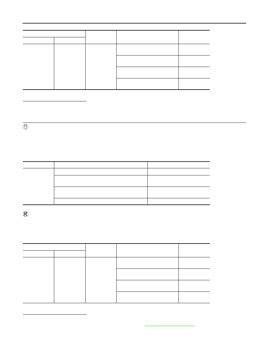
EM-24, "Exploded View"

.

ECM

Ground

Condition

Voltage

Connector

Terminal

F8

45

(MAF sensor 

signal)

Ground

Ignition switch ON (Engine 
stopped.)

Approx. 0.4 V

Idle (Engine is warmed-up to normal 
operating temperature.)

0.7 - 1.1 V

2,500 rpm (Engine is warmed-up to 
normal operating temperature.)

1.3 - 1.7 V

Idle to about 4,000 rpm

0.7 - 1.1 V to Ap-

prox. 2.4 V*

Monitor item

Condition

MAS A/F SE-B1

MAS A/F SE-B1

Ignition switch ON (Engine stopped.)

Approx. 0.4 V

Idle (Engine is warmed-up to normal operating temper-
ature.)

0.7 - 1.1 V

2,500 rpm (Engine is warmed-up to normal operating 
temperature.)

1.3 - 1.7 V

Idle to about 4,000 rpm

0.7 - 1.1 V to Approx. 2.4 V*

ECM

Ground

Condition

Voltage

Connector

Terminal

F8

45

(MAF sensor 

signal)

Ground

Ignition switch ON (Engine 
stopped.)

Approx. 0.4 V

Idle (Engine is warmed-up to normal 
operating temperature.)

0.7 - 1.1 V

2,500 rpm (Engine is warmed-up to 
normal operating temperature.)

1.3 - 1.7 V

Idle to about 4,000 rpm

0.7 - 1.1 V to Ap-

prox. 2.4 V*

P0111 IAT SENSOR

EC-159

< DTC/CIRCUIT DIAGNOSIS >

[MR18DE]

C

D

E

F

G

H

I

J

K

L

M

A

EC

N

P

O

P0111 IAT SENSOR

DTC Logic

INFOID:0000000009947273

DTC DETECTION LOGIC

DTC CONFIRMATION PROCEDURE

1.

INSPECTION START

Is it necessary to erase permanent DTC?

YES

>> GO TO 3.

NO

>> GO TO 2.

2.

PERFORM COMPONENT FUNCTION CHECK

Perform component function check. Refer to 

EC-160, "Component Function Check"

.

NOTE:
Use the component function check to check the overall function of the IAT sensor circuit. During this check, a
1st trip DTC might not be confirmed.

Is the inspection result normal?

YES

>> INSPECTION END

NO

>> Proceed to 

EC-160, "Diagnosis Procedure"

.

3.

PRECONDITIONING

If DTC CONFIRMATION PROCEDURE has been previously conducted, always perform the following proce-
dure before conducting the next test.
1.

Turn ignition switch OFF and wait at least 10 seconds.

2.

Turn ignition switch ON.

3.

Turn ignition switch OFF and wait at least 10 seconds.

TESTING CONDITION:
• Before performing the following procedure, do not add fuel.
• Before performing the following procedure, check that fuel level is between 1/4 and 4/4.
• Before performing the following procedure, confirm that battery voltage is 11 V or more at idle.

>> GO TO 4.

4.

PERFORM DTC CONFIRMATION PROCEDURE

1.

Start engine and let it idle for 60 minutes.

2.

Move the vehicle to a cool place.
NOTE:
Cool the vehicle in an environment of ambient air temperature between 

10

°

C (14

°

F) and 35

°

C (95

°

F).

3.

Turn ignition switch OFF and soak the vehicle for 12 hours.

CAUTION:

Never turn ignition switch ON during soaking.
NOTE:
The vehicle must be cooled with the food open.

4.

Start engine and let it idle for 5 minutes or more.

CAUTION:

Never turn ignition switch OFF during idling.

DTC No.

Trouble diagnosis

(Trouble diagnosis content)

DTC detecting condition

Possible cause

P0111

IAT SENSOR 1 B1
[Intake air temperature (IAT) 
sensor circuit range/perfor-
mance]

The comparison result of signals transmitted 
to ECM from each temperature sensor (IAT 
sensor, ECT sensor and FTT sensor, CVT 
fluid temperature sensor) shows that the volt-
age signal of the IAT sensor is higher/lower 
than that of other temperature sensors when 
the engine is started with its cold state.

• Harness or connectors

(High or low resistance in the IAT sen-
sor circuit)

• IAT sensor

EC-160

< DTC/CIRCUIT DIAGNOSIS >

[MR18DE]

P0111 IAT SENSOR

5.

Check 1st trip DTC.

Is 1st trip DTC detected?

YES

>> Proceed to 

EC-160, "Diagnosis Procedure"

.

NO

>> INSPECTION END

Component Function Check

INFOID:0000000009947274

1.

CHECK INTAKE AIR TEMPERATURE (IAT) SENSOR

1.

Turn ignition switch OFF.

2.

Disconnect mass air flow sensor harness connector.

3.

Check resistance between mass air flow sensor terminals as follows.

Is the inspection result normal?

YES

>> GO TO 2.

NO

>> Proceed to 

EC-160, "Diagnosis Procedure"

.

2.

CHECK INTERMITTENT INCIDENT

Check intermittent incident. Refer to 

GI-40, "Intermittent Incident"

.

Is the inspection result normal?

YES

>> INSPECTION END

NO

>> Proceed to 

EC-160, "Diagnosis Procedure"

.

Diagnosis Procedure

INFOID:0000000009947275

1.

CHECK INTAKE AIR TEMPERATURE (IAT) SENSOR

Check intake air temperature sensor. Refer to 

EC-160, "Component Inspection"

.

Is the inspection result normal?

YES

>> GO TO 2.

NO

>> Replace mass air flow sensor (with intake air temperature sensor). Refer to 

EM-24, "Exploded

View"

.

2.

CHECK INTERMITTENT INCIDENT

Check intermittent incident. Refer to 

GI-40, "Intermittent Incident"

.

>> INSPECTION END

Component Inspection

INFOID:0000000009947276

1.

CHECK INTAKE AIR TEMPERATURE (IAT) SENSOR

1.

Turn ignition switch OFF.

2.

Disconnect mass air flow sensor harness connector.

3.

Check resistance between mass air flow sensor terminals as follows.

Is the inspection result normal?

YES

>> INSPECTION END

NO

>> Replace mass air flow sensor (with intake air temperature sensor). Refer to 

EM-24, "Exploded

View"

.

Terminals

Condition

Resistance (k

)

1 and 2

Temperature [

°

C (

°

F)]

25 (77)

1.800 – 2.200

Terminals

Condition

Resistance (k

)

1 and 2

Temperature [

°

C (

°

F)]

25 (77)

1.800 – 2.200

P0112, P0113 IAT SENSOR

EC-161

< DTC/CIRCUIT DIAGNOSIS >

[MR18DE]

C

D

E

F

G

H

I

J

K

L

M

A

EC

N

P

O

P0112, P0113 IAT SENSOR

Description

INFOID:0000000009947277

The intake air temperature sensor is built-into mass air flow sensor
(1). The sensor detects intake air temperature and transmits a signal
to the ECM.
The temperature sensing unit uses a thermistor which is sensitive to
the change in temperature. Electrical resistance of the thermistor
decreases in response to the temperature rise.

<Reference data>

*: These data are reference values and are measured between ECM terminal 46
(Intake air temperature sensor) and ground.

DTC Logic

INFOID:0000000009947278

DTC DETECTION LOGIC

DTC CONFIRMATION PROCEDURE

1.

PRECONDITIONING

If DTC Confirmation Procedure has been previously conducted, always turn ignition switch OFF and wait at
least 10 seconds before conducting the next test.

>> GO TO 2.

2.

PERFORM DTC CONFIRMATION PROCEDURE

1.

Turn ignition switch ON and wait at least 5 seconds.

2.

Check 1st trip DTC.

Is 1st trip DTC detected?

YES

>> Go to 

EC-161, "Diagnosis Procedure"

.

NO

>> INSPECTION END

Diagnosis Procedure

INFOID:0000000009947279

1.

CHECK GROUND CONNECTION

1.

Turn ignition switch OFF.

2.

Check ground connection E38. Refer to 

GI-43, "Circuit Inspection"

.

PBIA9559J

Intake air temperature

[

°

C (

°

F)]

Voltage* (V)

Resistance (k

)

25 (77)

3.3

1.800 - 2.200

80 (176)

1.2

0.283 - 0.359

SEF012P

DTC No.

Trouble diagnosis name

DTC detecting condition

Possible cause

P0112

Intake air temperature 
sensor circuit low input

An excessively low voltage from the sensor is 
sent to ECM.

• Harness or connectors

(The sensor circuit is open or shorted.)

• Intake air temperature sensor

P0113

Intake air temperature 
sensor circuit high input

An excessively high voltage from the sensor is 
sent to ECM.


Content   ..  316  317  318  319   ..