Nissan Cube. Manual - part 316
EC-150
< DTC/CIRCUIT DIAGNOSIS >
[MR18DE]
P0101 MAF SENSOR
1.
Turn ignition switch OFF.
2.
Disconnect ECM harness connector.
3.
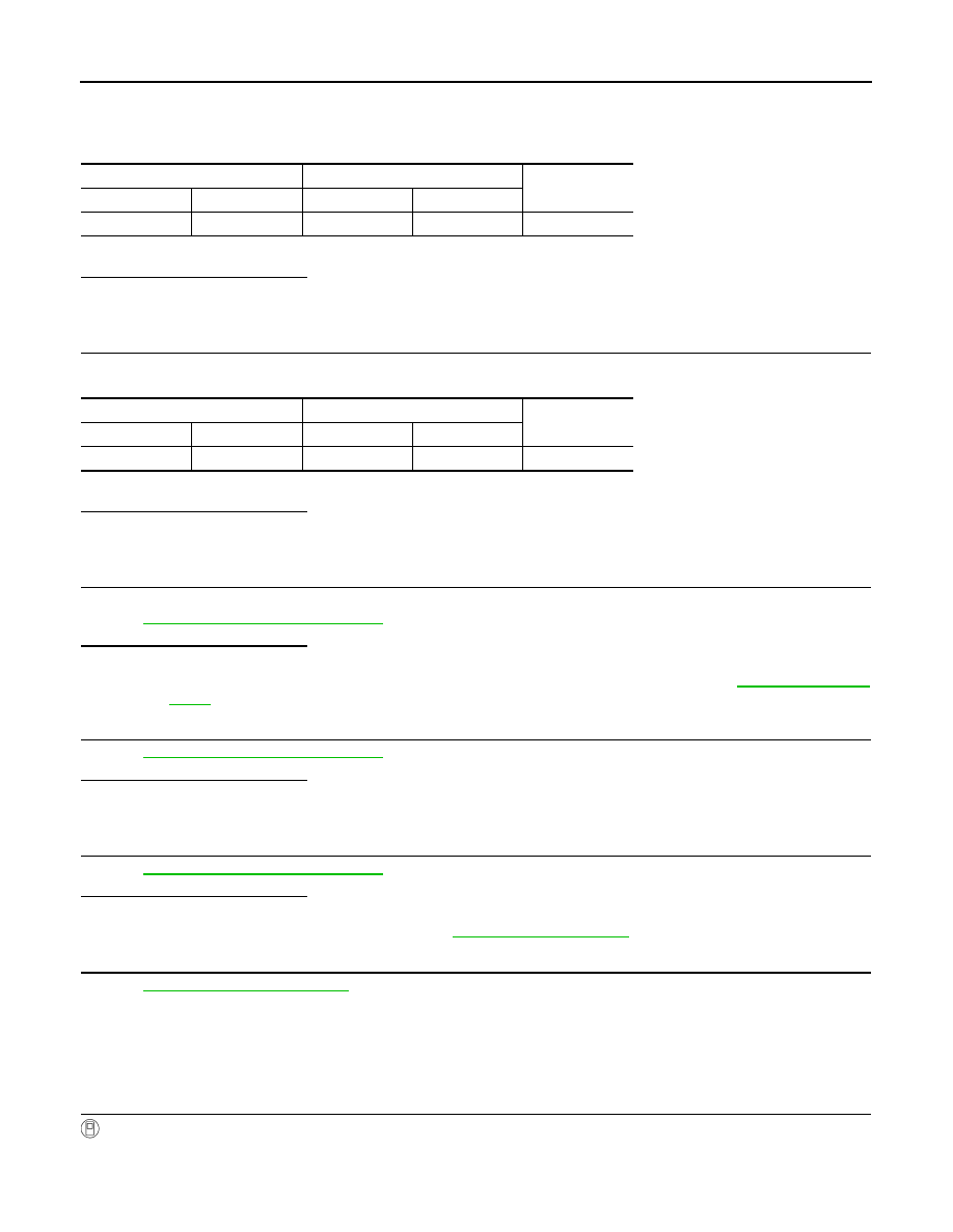
Check the continuity between MAF sensor harness connector and ECM harness connector.
4.
Also check harness for short to ground and short to power.
Is the inspection result normal?
YES
>> GO TO 7.
NO
>> Repair open circuit or short to ground or short to power in harness or connectors.
7.
CHECK MAF SENSOR INPUT SIGNAL CIRCUIT FOR OPEN AND SHORT
1.
Check the continuity between MAF sensor harness connector and ECM harness connector.
2.
Also check harness for short to ground and short to power.
Is the inspection result normal?
YES
>> GO TO 8.
NO
>> Repair open circuit or short to ground or short to power in harness or connectors.
8.
CHECK INTAKE AIR TEMPERATURE SENSOR
Check intake air temperature sensor.
Refer to
EC-162, "Component Inspection"
Is the inspection result normal?
YES
>> GO TO 9.
NO
>> Replace mass air flow sensor (with intake air temperature sensor). Refer to
9.
CHECK EVAP CONTROL SYSTEM PRESSURE SENSOR
EC-279, "Component Inspection"
Is the inspection result normal?
YES
>> GO TO 10.
NO
>> Replace EVAP control system pressure sensor.
10.
CHECK MASS AIR FLOW SENSOR
EC-150, "Component Inspection"
Is the inspection result normal?
YES
>> GO TO 11.
NO
>> Replace mass air flow sensor. Refer to
.
11.
CHECK INTERMITTENT INCIDENT
GI-40, "Intermittent Incident"
>> INSPECTION END
Component Inspection
INFOID:0000000009947268
1.
CHECK MASS AIR FLOW SENSOR-I
With CONSULT
1.
Turn ignition switch OFF.
2.
Reconnect all harness connectors disconnected.
MAF sensor
ECM
Continuity
Connector
Terminal
Connector
Terminal
F4
4
F8
52
Existed
MAF sensor
ECM
Continuity
Connector
Terminal
Connector
Terminal
F4
3
F8
45
Existed