Nissan Cube. Manual - part 1008


  Index      Nissan     Nissan Cube (2014 year) - Service and Repair Manual


Search            


Content   ..  1006  1007  1008  1009   ..


Nissan Cube. Manual - part 1008


WCS

COMBINATION METER

WCS-35

< ECU DIAGNOSIS INFORMATION >

C

D

E

F

G

H

I

J

K

L

M

B

A

O

P

NOTE:

Some items are not available according to vehicle specification.
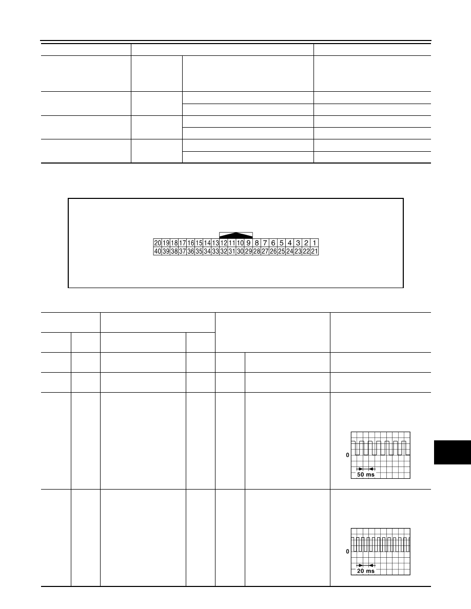
TERMINAL LAYOUT

PHYSICAL VALUES

OUTSIDE TEMP
[

°

C or 

°

F]

Ignition switch 
ON

Equivalent to ambient temperature
NOTE:
This may not match the indicated value 
on the information display.

FUEL LOW SIG

Ignition switch 
ON

Low fuel warning displayed

On

Low fuel warning not displayed

Off

BUZZER

Ignition switch 
ON

Buzzer ON

On

Buzzer OFF

Off

TPMS PRESS L

Ignition switch 
ON

Low tire pressure warning display ON

On

Low tire pressure warning display OFF

Off

Monitor Item

Condition

Value/Status

JSNIA0623ZZ

Terminal No.

(Wire color)

Description

Condition

Value

(Approx.)

+

Signal name

Input/

Output

1

(L)

CAN-H

2

(P)

CAN-L

3

(V)

Ground

Vehicle speed signal
(2-pulse)

Output

Ignition 
switch 
ON

Speedometer operated 
[When vehicle speed is ap-
prox. 40 km/h (25 MPH)]

NOTE:
The maximum voltage varies de-
pending on the specification 
(destination unit).

4

(V/R)

*1

(L)

*2

Ground

Vehicle speed signal
(8-pulse)

Output

Ignition 
switch 
ON

Speedometer operated 
[When vehicle speed is ap-
prox. 40 km/h (25 MPH)]

NOTE:
The maximum voltage varies de-
pending on the specification 
(destination unit).

JSNIA0015GB

JSNIA0012GB

WCS-36

< ECU DIAGNOSIS INFORMATION >

COMBINATION METER

6

(BR/Y)

Ground

Fuel level sensor signal

Input

Ignition 
switch 
ON

7

(R/G)

Ground

Air bag signal

Input

Ignition 
switch 
ON

Air bag warning lamp
ON

5 V

Air bag warning lamp
OFF

0 V

8

(P)

Ground

Overdrive control switch 
signal

Input

Ignition 
switch 
ON

Overdrive control switch 
ON

4 V

Overdrive control switch 
OFF

0 V

9

(O)

Ground

Seat belt buckle switch sig-
nal (driver side)

Input

Ignition 
switch 
ON

When driver seat belt is fas-
tened.

12 V

When driver seat belt is un-
fastened.

0 V

10

(SB)

Ground

Parking brake switch signal

Input

Engine 
idling

Parking brake applied.

0 V

Parking brake released.

5 V

11

(G/R)

Ground

Brake fluid level switch sig-
nal

Input

Ignition 
switch 
ON

Brake fluid level is normal

12 V

Brake fluid level is less than 
LOW level

0 V

13

(B/R)

Ground

Illumination control signal

Output

Ignition 
switch 
ON

• Lighting switch 1ST
• When meter illumination 

is maximum

• Lighting switch 1ST
• When meter illumination 

is step 11

• Lighting switch 1ST
• When meter illumination 

is minimum

12 V

15

(L/Y)

Ground

ACC power supply

Input

Ignition 
switch 
ACC

Battery voltage

18

(R/Y)

Ground

Security signal

Input

Ignition 
switch 
ON

Security warning lamp ON

0 V

Security warning lamp OFF

12 V

Terminal No.

(Wire color)

Description

Condition

Value

(Approx.)

+

Signal name

Input/

Output

JPNIA1546ZZ

JPNIA1687GB

JPNIA1686GB

WCS

COMBINATION METER

WCS-37

< ECU DIAGNOSIS INFORMATION >

C

D

E

F

G

H

I

J

K

L

M

B

A

O

P

19

(PU/W)

Ground

Ambient sensor signal

Input

Ignition 
switch 
ON

Changes depending to am-
bient temperature.

20

(R/W)

Ground

Ambient sensor ground

Ignition 
switch 
ON

0  V

21

(B)

Ground

Ground

Ignition 
switch 
ON

0  V

22

(B)

Ground

Ground

Ignition 
switch 
ON

0  V

23

(B)

Ground

Ground

Ignition 
switch 
ON

0  V

24

(PU)

Ground

Fuel level sensor signal 
ground

Ignition 
switch 
ON

0  V

25

(B)

Ground

VDC ground

Ignition 
switch 
ON

0  V

27

(LG/R)

Ground

Battery power supply

Input

Ignition 
switch 
OFF

Battery voltage

28

(GR)

Ground

Ignition signal

Input

Ignition 
switch 
ON

Battery voltage

29

(BR)

Ground

Passenger seat belt warn-
ing signal

Input

Ignition 
switch 
ON

• When getting in the pas-

senger seat.

• When passenger seat 

belt is fastened.

12 V

• When getting in the pas-

senger seat.

• When passenger seat 

belt is unfastened.

0 V

31

(R)

Ground

A/C auto amp. connection 
recognition signal

Input

Ignition 
switch 
ON

5  V

Terminal No.

(Wire color)

Description

Condition

Value

(Approx.)

+

Signal name

Input/

Output

JSNIA0014GB

WCS-38

< ECU DIAGNOSIS INFORMATION >

COMBINATION METER

• *1: With NAVI
• *2: Without NAVI

35

(BR)

Ground

Engine coolant tempera-
ture signal

Output

Ignition 
switch 
ON

Engine idling [Approximate-
ly 20

°

C (68

°

F)]

Engine idling [Approximate-
ly 80

°

C (176

°

F)]

0 V

38

(GR)

Ground

Alternator signal

Input

Ignition 
switch 
ON

Charge warning lamp ON

0 V

Charge warning lamp OFF

12 V

Terminal No.

(Wire color)

Description

Condition

Value

(Approx.)

+

Signal name

Input/

Output

PKID0590E

SKIB3651J


Content   ..  1006  1007  1008  1009   ..