Nissan Cube. Manual - part 36
AV
ANTENNA BASE
AV-137
< REMOVAL AND INSTALLATION >
[AUDIO WITH NAVIGATION]
C
D
E
F
G
H
I
J
K
L
M
B
A
O
P
ANTENNA BASE
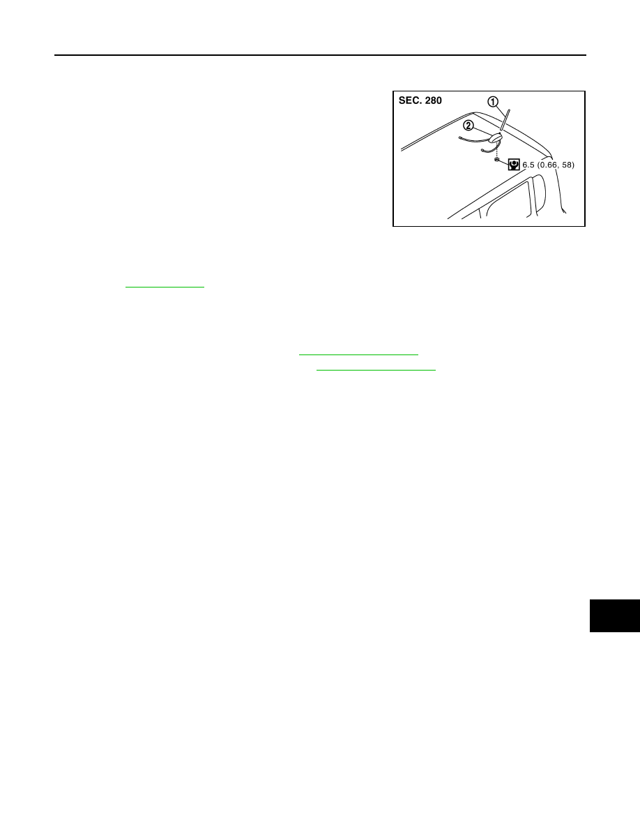
Exploded View
INFOID:0000000009949645
Removal and Installation
INFOID:0000000009949646
REMOVAL
1.
Remove luggage side upper finisher. Refer to
2.
Remove assist grip and headlining clips. Refer to
3.
Pull headlining (rear). Obtain a service area.
4.
Remove antenna base mounting nut.
5.
Remove antenna base.
INSTALLATION
Install in the reverse order of removal.
CAUTION:
If the antenna base mounting nut is tightened looser than the specified torque, then this will lower the
sensitivity of the antenna. On the other hand, if the nut is tightened tighter than the specified torque,
then this will deform the roof panel.
JPNIA1699GB
1.
Antenna rod
2.
Antenna base
for symbols in the figure.