Nissan Versa Note. Manual - part 842


  Index      Nissan     Nissan Versa Note (2014 year) - Service and Repair Manual


Search            


Content   ..  840  841  842  843   ..


Nissan Versa Note. Manual - part 842


TM-248

< REMOVAL AND INSTALLATION >

[CVT: RE0F11A]

WATER HOSE

6. Remove the bracket.

INSTALLATION

Installation is in the reverse order of removal.

CAUTION:

• Do not reuse hose clamps.

• Do not reuse clips.

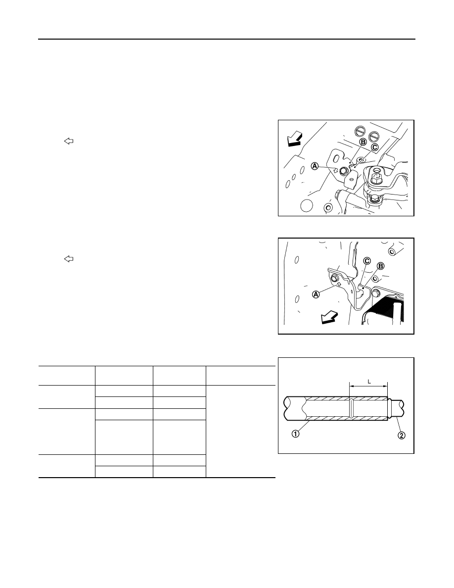
• When installing bracket A to the transaxle assembly.

- Face arrow (A) of bracket A toward the front of the vehicle.

- Set baffle (B) of bracket A to rib (C) of transaxle.

• When installing the bracket B to the transaxle assembly.

- Face arrow (A) of bracket A towards the top of vehicle.

- Insert baffle (B) into the boss hole (C) of transaxle.

• Refer to the following when installing water hoses.

• Refer to the following when installing hose clamp.

CAUTION:

Hose clamp should not interfere with the bulge of fluid cooler tube.

:  Front

JSDIA4112ZZ

:  Front

JSDIA4113ZZ

Water hose (1)

Installation side 

tube (2)

Direction of paint 

mark

Hose insertion depth 

(L)

Water hose A

Water outlet

Upward

(A): 27 mm (1.06 in) 
(End reaches the 2-
stage bulge.)

CVT oil warmer

Frontward

Water hose B

CVT oil warmer

Frontward

Water bypass pipe

Rightward (Align 
with the mark of 
the water by-
pass pipe side)

Water hose C

Water bypass pipe

Water outlet

Upward

JSDIA2459ZZ

WATER HOSE

TM-249

< REMOVAL AND INSTALLATION >

[CVT: RE0F11A]

C

E

F

G

H

I

J

K

L

M

A

B

TM

N

O

P

Inspection

INFOID:0000000009019801

INSPECTION AFTER INSTALLATION

Start the engine and check visually that there is no leakage of engine coolant.

Water hose (1)

Installation side 

tube (2)

Hose clamp (3)

Dieection of tab

Clamping position

Water hose A

Water outlet

Upward

5 - 7 mm (0.20 - 0.28 
in) (A) from hose end

CVT oil warmer

Frontward

Water hose B

CVT oil warmer

Leftward

Water bypass pipe Rightward

Water hose C

Water bypass pipe

Upward and 45

° 

frontward

Water outlet

Upward and 45

° 

frontward

JSDIA2424ZZ

TM-250

< REMOVAL AND INSTALLATION >

[CVT: RE0F11A]

FLUID COOLER HOSE

FLUID COOLER HOSE

Exploded View

INFOID:0000000009300290

Removal and Installation

INFOID:0000000009300291

NOTE:

When removing components such as hoses, tubes/lines, etc., cap or plug openings to prevent fluid from spill-

ing.

REMOVAL

1. Remove the front bumper fascia. Refer to 

EXT-24, "Removal and Installation"

.

2. Disconnect CVT fluid cooler hoses.
3. Remove CVT fluid cooler bolts.
4. Remove CVT fluid cooler.

INSTALLATION

Installation is in the reverse order of removal.

After installation be sure to check the CVT fluid and add the specified CVT fluid as necessary. Refer to 

TM-

226, "Inspection"

.

CAUTION:

Do not reuse hose clamps.

Inspection and Adjustment

INFOID:0000000009300292

INSPECTION AFTER INSTALLATION

Check for CVT fluid leakage. Refer to 

TM-226, "Inspection"

.

ADJUSTMENT AFTER INSTALLATION

Adjust the CVT fluid level. Refer to 

TM-227, "Adjustment"

.

1.

CVT fluid cooler

2.

Hoses

ALDIA0228ZZ

PLUG

TM-251

< REMOVAL AND INSTALLATION >

[CVT: RE0F11A]

C

E

F

G

H

I

J

K

L

M

A

B

TM

N

O

P

PLUG

Description

INFOID:0000000009019802

Replace the O-ring if oil leakage or exudes from the plug.

Exploded View

INFOID:0000000009019803

Removal and Installation

INFOID:0000000009019804

REMOVAL

Remove the plugs and O-rings.

INSTALLATION

Installation is in the reverse order of removal.

CAUTION:

• Do not reuse O-rings.

• Apply Genuine NISSAN CVT Fluid NS-3 to O-rings.

Inspection and Adjustment

INFOID:0000000009019805

INSPECTION AFTER INSTALLATION

Check for CVT fluid leakage. Refer to 

TM-226, "Inspection"

.

ADJUSTMENT AFTER INSTALLATION

Adjust the CVT fluid level. Refer to 

TM-227, "Adjustment"

.

1.

Plug

2.

O-ring

3.

O-ring

4.

Plug

Genuine NISSAN CVT Fluid NS-3

JSDIA1889GB


Content   ..  840  841  842  843   ..