Nissan Versa Note. Manual - part 760
STEERING COLUMN
ST-9
< REMOVAL AND INSTALLATION >
C
D
E
F
H
I
J
K
L
M
A
B
ST
N
O
P
STEERING COLUMN
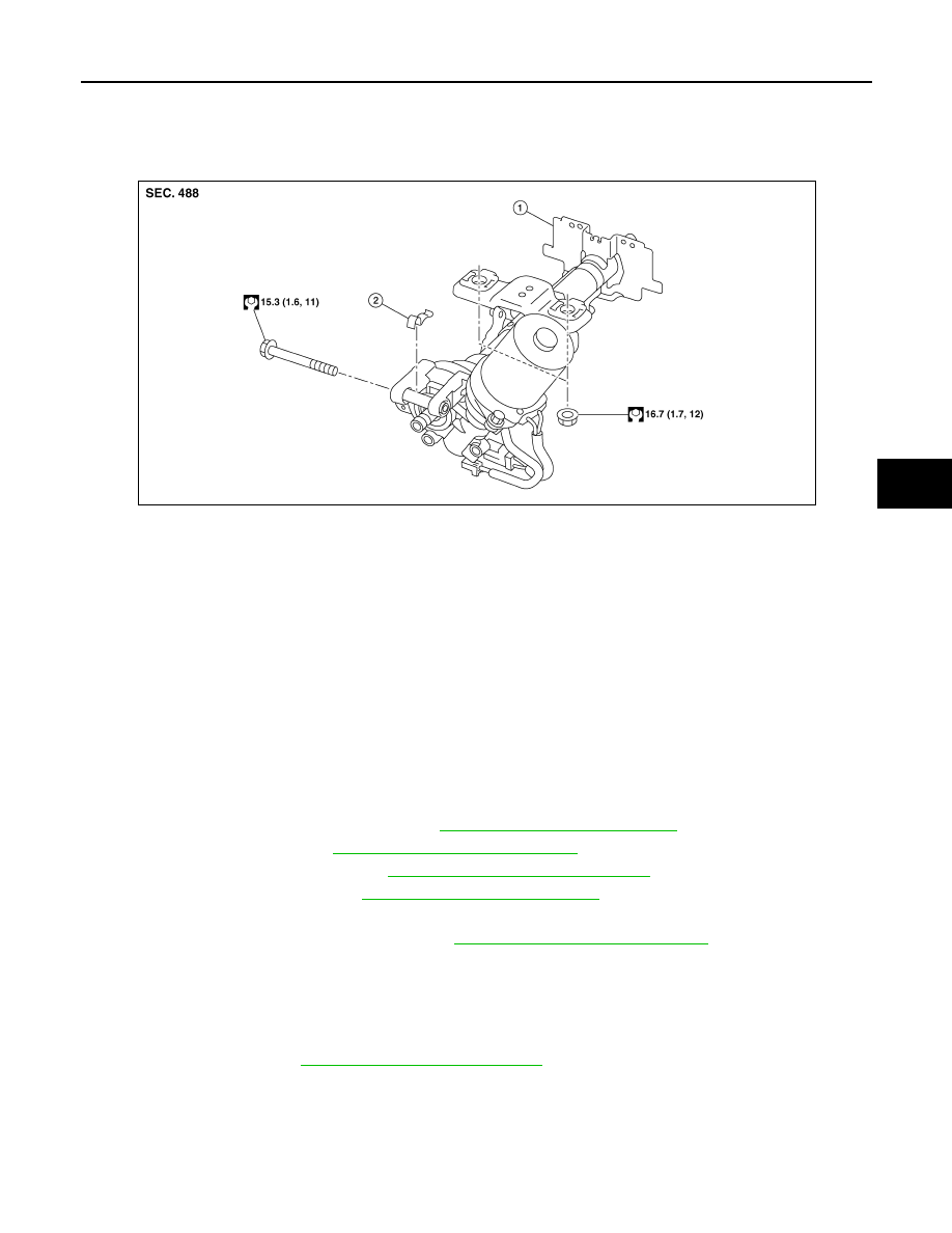
Exploded View
INFOID:0000000009385534
Removal and Installation
INFOID:0000000009385535
CAUTION:
• Any time the ignition switch has been disconnected, removed or installed; the vehicle keys must be
re-registered in the BCM. Refer to CONSULT operations manual.
• Care must be taken not to rotate the steering gear during the removal or installation of the steering
column.
• Care must be taken not to allow axial impact to the steering column during removal or installation.
REMOVAL
1. Set the front wheels and tires in the straight-ahead position.
2. Set the steering column tilt to the lowest position.
CAUTION:
Securely lock the tilt lever.
3. Remove instrument lower panel LH. Refer to
IP-24, "Removal and Installation"
4. Remove spiral cable. Refer to
SR-15, "Removal and Installation"
.
5. Remove combination switch. Refer to
EXL-103, "Removal and Installation"
.
6. Remove the cluster lid A. Refer to
IP-21, "Removal and Installation"
.
7. Disconnect the switch harness connectors.
8. Remove the key cylinder if necessary. Refer to
TM-235, "Removal and Installation"
.
9. Set the steering column tilt to the middle position.
CAUTION:
Do not change the position of the tilt mechanism until the steering column is reinstalled.
10. Loosen the steering shaft lower joint bolt.
11. Remove the steering intermediate shaft upper bolt and separate the steering intermediate shaft from the
steering column. Refer to
ST-12, "Removal and Installation"
.
CAUTION:
• Place a matching mark on both steering intermediate shaft and steering column before removing
the steering intermediate shaft.
• When removing steering intermediate shaft, do not insert any tool into the yoke groove to pull
out the steering intermediate shaft or damage could occur. Replace steering intermediate shaft if
damaged.
1.
Steering column
2.
Clamp
AWGIA0294ZZ