Nissan Versa Note. Manual - part 761


  Index      Nissan     Nissan Versa Note (2014 year) - Service and Repair Manual


Search            


Content   ..  759  760  761  762   ..


Nissan Versa Note. Manual - part 761


STEERING SHAFT

ST-13

< REMOVAL AND INSTALLATION >

C

D

E

F

H

I

J

K

L

M

A

B

ST

N

O

P

• Before installation, check that steering column tilt is in the middle position.

• For intermediate shaft bolt, and lower joint bolt direction, refer to 

ST-12, "Exploded View"

.

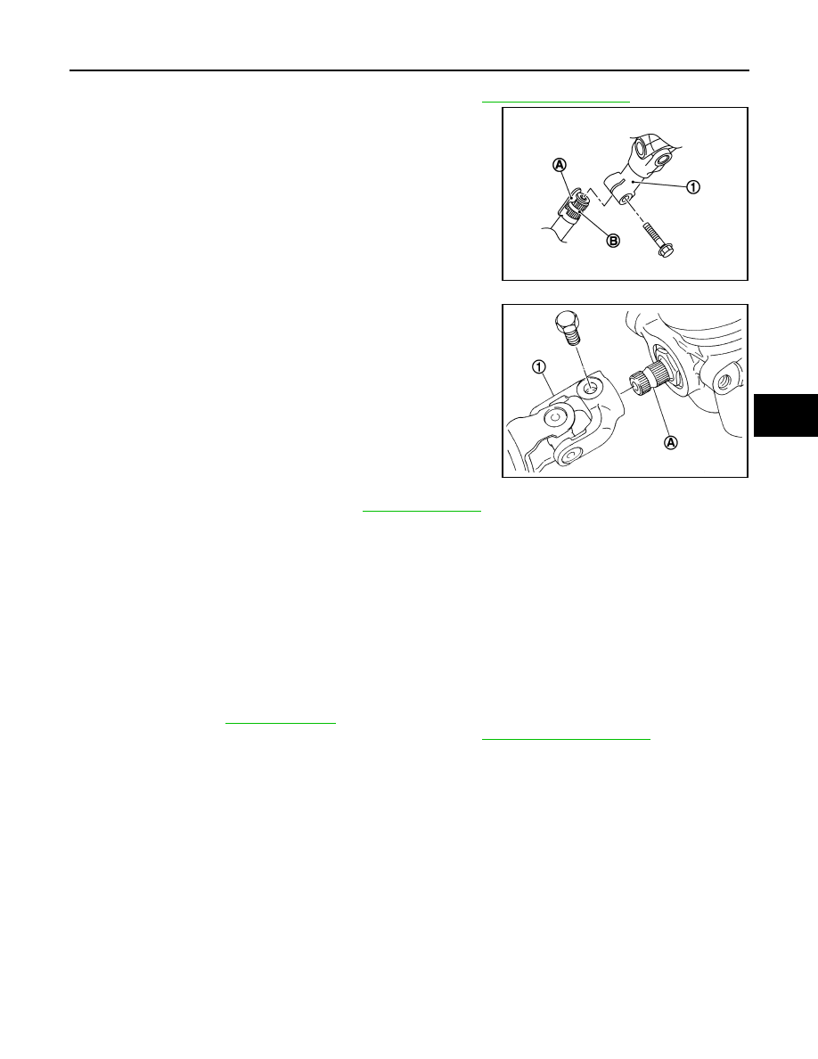
• To install align the steering gear guide protrusion (A) with the

groove of lower joint (1), make sure the bolt is securely seated in

groove (B) of steering gear before final tightening.

CAUTION:

If a guide protrusion is not included, align with the matching

mark placed at the removal step.

• When tightening lower joint bolt to the steering gear lower shaft,

temporarily tighten it and make sure there is no sticking or galling

before final tightening.

• When connecting intermediate shaft upper side (1) and column

shaft, make sure the bolt is securely seated in groove (A) of col-

umn shaft before final tightening.

• Perform inspection after installation. Refer to 

ST-13, "Inspection"

.

Inspection

INFOID:0000000009385539

INSPECTION AFTER REMOVAL

• Check each part of steering intermediate shaft, lower joint, and steering column for damage or other mal-

functions. Replace if there are any abnormal conditions.

INSPECTION AFTER INSTALLATION

• Rotate steering wheel to make sure it is centered and there is no binding, noise or excessive steering effort.

• Make sure that the number of turns are the same from the straight-ahead position to the left and right locks.

• Check each part of steering intermediate shaft, lower joint, and steering column for damage or other mal-

functions. Replace if there are any abnormal conditions.

• Check the steering wheel play, neutral position steering wheel, steering wheel turning force, and front wheel

turning angle. Refer to 

ST-5, "Inspection"

.

• Check the neutral position of the steering angle sensor. Refer to 

BRC-53, "Work Procedure"

.

JPGIA0041ZZ

SGIA1295E

ST-14

< REMOVAL AND INSTALLATION >

STEERING GEAR AND LINKAGE

STEERING GEAR AND LINKAGE

Exploded View

INFOID:0000000009385540

Removal and Installation

INFOID:0000000009385541

CAUTION:

• Spiral cable may be cut if steering wheel turns while separating steering column and steering gear;

Always secure the steering wheel using string to avoid turning.

• Place a matching mark on both lower joint and steering gear before removing lower joint.

• When removing lower joint, do not place any tool into the yoke groove to pull out the lower joint.

Replace the lower joint if damaged.

REMOVAL

1. Set the front wheels and tires in the straight-ahead position.
2. Set the steering column tilt to the middle position.

CAUTION:

Securely lock the tilt lever.

3. Remove front suspension member. Refer to 

FSU-14, "Removal and Installation"

.

4. Remove the steering gear bolts and nuts and separate the steering gear from the front suspension mem-

ber.

5. Separate cowl seal from steering gear if necessary.

INSTALLATION

Installation is in the reverse order of removal.

CAUTION:

• During installation, finger-tighten all of the bracket and joint retaining bolts; then tighten them to

specification. Do not apply undue stress to the steering column.

• The guide protrusion is not required to be reinstalled.

• Before installation, check that the steering column tilt is in the middle position.

• Clean mating surface on the body side of cowl seal when installing steering gear assembly. 

• Inspect steering gear after installation. Refer to 

ST-14, "Inspection"

.

Inspection

INFOID:0000000009385542

INSPECTION AFTER REMOVAL

• Check each part of steering gear for damage or other malfunctions. Replace if there are any abnormal con-

ditions. Refer to 

ST-14, "Inspection"

.

1.

Guide

2.

Cowl seal

3.

Steering gear

4.

Front suspension member

Front

AWGIA0236ZZ

STEERING GEAR AND LINKAGE

ST-15

< REMOVAL AND INSTALLATION >

C

D

E

F

H

I

J

K

L

M

A

B

ST

N

O

P

INSPECTION AFTER INSTALLATION

• Rotate steering wheel to make sure it is centered and there is no binding, noise or excessive steering effort.

• Make sure that the number of turns are the same from the straight-ahead position to the left and right locks.

• Check each part of steering system for damage or other malfunctions. Replace if there are any abnormal

conditions.

• Check the steering wheel play, neutral position steering wheel, steering wheel turning force, and front wheel

turning angle. Refer to 

ST-5, "Inspection"

.

• Check wheel alignment. Refer to 

FSU-8, "Adjustment"

.

• Check the neutral position of the steering angle sensor. Refer to 

BRC-53, "Work Procedure"

.

ST-16

< UNIT DISASSEMBLY AND ASSEMBLY >

STEERING GEAR AND LINKAGE

UNIT DISASSEMBLY AND ASSEMBLY

STEERING GEAR AND LINKAGE

Exploded View

INFOID:0000000009385543

Disassembly and Assembly

INFOID:0000000009385544

DISASSEMBLY

1. Remove outer socket lock nut and outer socket.

CAUTION:

When loosening outer socket lock nut, be sure to hold outer socket with a suitable tool to prevent

ball joint from contacting knuckle.

2. Remove inner boot clamp, outer boot clamp and remove boot.

CAUTION:

Do not damage inner socket or steering gear housing when removing boot.

3. Remove inner socket.

ASSEMBLY

1. Apply (Autolex A or Dow Corning 111) or equivalent to inner socket and turn pinion fully to retract inner

socket into gear housing assembly.

CAUTION:

Make sure there are no contaminants in the grease, on the inner socket, or inside the steering gear

housing. 

1.

Joint cover

2.

Steering gear

3.

Inner socket

4.

Inner boot clamp

5.

Boot

6.

Outer boot clamp

7.

Outer socket

ALGIA0098GB


Content   ..  759  760  761  762   ..