Nissan Versa Note. Manual - part 729


  Index      Nissan     Nissan Versa Note (2014 year) - Service and Repair Manual


Search            


Content   ..  727  728  729  730   ..


Nissan Versa Note. Manual - part 729


DRIVER AIR BAG MODULE

SR-13

< REMOVAL AND INSTALLATION >

C

D

E

F

G

I

J

K

L

M

A

B

SR

N

O

P

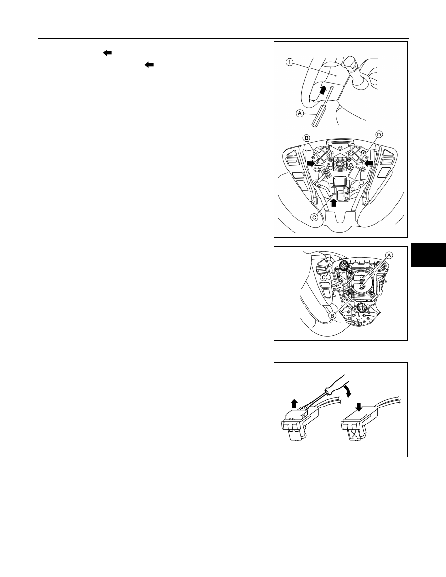
2. Locate the access holes on side of steering wheel rear finisher

(1) and insert (

) a 5.0 mm (0.20 in) diameter suitable tool (A).

3. Push suitable tool inward (

) and make sure the tool contacts

the spring (D). While pushing on spring (D), push on the driver

air bag module. The driver air bag module hook will release,

then pull to release from steering wheel. Repeat procedure on

springs (B) and (C).

NOTE:

Driver air bag module removed for clarity.

4. Lift driver air bag module away from the steering wheel and dis-

connect the driver air bag module harness connectors (A) and

the horn harness connector (B). Then remove the harnesses

from hook (C).

NOTE:

Take note of harness routing for correct installation.

CAUTION:

• For removing/installing the driver air bag module harness

connector, insert a thin screwdriver wrapped in tape into

the notch, then lift the lock and remove the harness con-

nector as shown.

• Install the harness connector with the lock raised, and

push the lock into the connector as shown.

• After installing the connector, check that the lock is

pushed in securely.

AWHIA0528ZZ

AWHIA0551ZZ

PHIA0953J

SR-14

< REMOVAL AND INSTALLATION >

DRIVER AIR BAG MODULE

5. Remove the driver air bag module.

CAUTION:

• Always place the driver air bag module with pad side fac-

ing upward.

: Upward

• Replace the driver air bag module if it has been dropped

or sustained an impact.

• Do not strike the driver air bag module.

INSTALLATION

Installation is in the reverse order of removal.

NOTE:

To install the driver air bag module onto the steering wheel, align the hooks over the springs and push to snap

into place.

CAUTION:

• Always route driver air bag module harness in original location. 

• Be careful not to damage or pinch the harness while installing.

• After the work is completed, check the function of the horn and each steering switch.

• After the work is completed, perform diagnosis to check that no malfunction is detected. Refer to

SRC-14, "Description"

.

JMHIA2077ZZ

JMHIA0009ZZ

SPIRAL CABLE

SR-15

< REMOVAL AND INSTALLATION >

C

D

E

F

G

I

J

K

L

M

A

B

SR

N

O

P

SPIRAL CABLE

Exploded View

INFOID:0000000008969284

Removal and Installation

INFOID:0000000008969285

WARNING:

• Before servicing the SRS, turn ignition switch OFF, disconnect both battery terminals then wait at

least three minutes.

• Do not disassemble the spiral cable.

• Do not use air tools or electric tools for servicing.

CAUTION:

• Do not allow oil, grease, detergent or water to come in contact with the spiral cable.

REMOVAL

1. Disconnect negative and positive battery terminals, then wait at least three minutes. Refer to 

PG-67,

"Removal and Installation (Battery)"

.

2. Remove steering wheel. Refer to 

ST-8, "Removal and Installation"

.

3. Remove steering column covers. Refer to 

IP-17, "Removal and Installation"

.

4. Disconnect the harness connector (A) from spiral cable and har-

ness connector (B) from steering angle sensor.

1.

Combination switch

2.

Steering angle sensor

3.

Spiral cable

Pawl

AWHIA0504ZZ

ALHIA0272ZZ

SR-16

< REMOVAL AND INSTALLATION >

SPIRAL CABLE

5. Remove screws (A), then release pawls and remove spiral cable

and steering angle sensor (1) as an assembly.

: Pawl

CAUTION:

Do not turn the spiral cable quickly or beyond the limit

number of turns (approximately 2.5 turns from the neutral

position), this may cause the cable to snap.

6. Remove screws (A), then release pawls (B) and separate the

steering angle sensor (2) from spiral cable (1).

CAUTION:

Do not reuse steering angle sensor.

CAUTION:

• Do not strike or drop the spiral cable.

• Replace the spiral cable if it has been dropped or sustained

an impact.

INSTALLATION

Installation is in the reverse order of removal.

• The turn signal lever must be in the neutral position for spiral cable installation.

AWHIA0538ZZ

ALHIA0271ZZ

JMHIA0009ZZ


Content   ..  727  728  729  730   ..