Nissan Versa Note. Manual - part 650
PWC-36
< DTC/CIRCUIT DIAGNOSIS >
POWER WINDOW MOTOR
NO
>> Repair or replace harness.
REAR LH
REAR LH : Component Function Check
INFOID:0000000009693676
1.
CHECK FUNCTION
Check rear power window motor LH operation with power window main switch or rear power window switch
LH.
Is the inspection result normal?
YES
>> Inspection End.
NO
>> Refer to
PWC-36, "REAR LH : Diagnosis Procedure"
REAR LH : Diagnosis Procedure
INFOID:0000000009693677
Regarding Wiring Diagram information, refer to
.
1.
CHECK REAR POWER WINDOW MOTOR LH INPUT SIGNAL
1. Turn ignition switch OFF.
2. Disconnect rear power window motor LH connector.
3. Turn ignition switch ON.
4. Check voltage between rear power window motor LH harness connector and ground.
Is the inspection result normal?
YES
>> Replace rear power window motor LH.
NO
>> GO TO 2.
2.
CHECK REAR POWER WINDOW MOTOR LH CIRCUIT
1. Turn ignition switch OFF.
2. Disconnect rear power window switch LH connector.
3. Check continuity between rear power window switch LH harness connector and rear power window motor
LH harness connector.
4. Check continuity between rear power window switch LH connector and ground.
Is the inspection result normal?
YES
>> Replace rear power window switch LH. Refer to
PWC-58, "Removal and Installation"
.
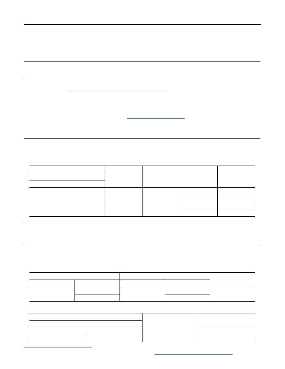
(+)
(-)
Condition
Voltage (V)
(Approx.)
Rear power window motor LH
Connector
Terminal
D204
1
Ground
Rear power win-
dow switch LH
NEUTRAL
0
UP
Battery voltage
2
NEUTRAL
0
DOWN
Battery voltage
Rear power window switch LH
Rear power window motor LH
Continuity
Connector
Terminal
Connector
Terminal
D203
6
D204
2
Yes
5
1
Rear power window switch LH
Ground
Continuity
Connector
Terminal
D203
6
No
5