Nissan Versa Note. Manual - part 648


  Index      Nissan     Nissan Versa Note (2014 year) - Service and Repair Manual


Search            


Content   ..  646  647  648  649   ..


Nissan Versa Note. Manual - part 648


PWC-28

< DTC/CIRCUIT DIAGNOSIS >

POWER SUPPLY AND GROUND CIRCUIT

Is the inspection result normal?

YES

>> Inspection End.

NO

>> GO TO 2.

2.

CHECK FRONT POWER WINDOW SWITCH RH POWER SUPPLY CIRCUIT

1. Turn ignition switch OFF.

2. Disconnect BCM connector.

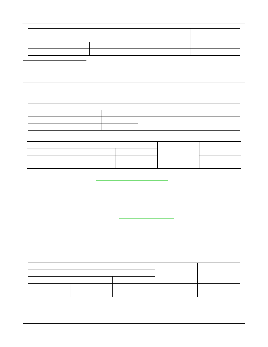
3. Check continuity between BCM harness connector and front power window switch RH harness connector.

4. Check continuity between BCM harness connector and ground.

Is the inspection result normal?

YES

>> Replace BCM. Refer to 

BCS-70, "Removal and Installation"

.

 NO

>> Repair or replace harness.

REAR POWER WINDOW SWITCH
REAR POWER WINDOW SWITCH : Diagnosis Procedure

INFOID:0000000009693665

Regarding Wiring Diagram information, refer to 

PWC-16, "Wiring Diagram"

.

1.

CHECK REAR POWER WINDOW SWITCH POWER SUPPLY

1. Turn ignition switch OFF.

2. Disconnect rear power window switch connector.

3. Turn ignition switch ON.

4. Check voltage between rear power window switch harness connector and ground.

Is the inspection result normal?

YES

>> Inspection End.

NO

>> GO TO 2.

2.

CHECK REAR POWER WINDOW SWITCH POWER SUPPLY CIRCUIT

1. Turn ignition switch OFF.

2. Disconnect BCM connector.

(+)

(-)

Voltage

(Approx.)

Front power window switch RH

Connector

Terminal

D105

8

Ground

Battery voltage

BCM

Front power window switch RH

Continuity

Connector

Terminal

 Connector

Terminal

M99 (with Intelligent Key system)

68

D105

8

Yes

M19 (without Intelligent Key system)

52

BCM

Ground

Continuity

Connector

Terminal

M99 (with Intelligent Key system)

68

No

M19 (without Intelligent Key system)

52

(+)

(-)

Voltage (V)

(Approx.)

Rear power window switch 

Connector

Terminal

LH

D203

4

Ground

Battery voltage

RH

D303

POWER SUPPLY AND GROUND CIRCUIT

PWC-29

< DTC/CIRCUIT DIAGNOSIS >

C

D

E

F

G

H

I

J

L

M

A

B

PWC

N

O

P

3. Check continuity between BCM harness connector and rear power window switch harness connector.

4. Check continuity between BCM harness connector and ground.

Is the inspection result normal?

YES

>> Replace BCM. Refer to 

BCS-70, "Removal and Installation"

.

NO

>> Repair or replace harness.

BCM

Rear power window switch

Continuity

Connector

Terminal

Connector

Terminal

M99 (with Intelligent Key system)

68

LH

D203

4

Yes

RH

D303

M19 (without Intelligent Key system)

52

LH

D203

RH

D303

BCM

Ground

Continuity

Connector

Terminal

M99 (with Intelligent Key system)

68

No

M19 (without Intelligent Key system)

52

PWC-30

< DTC/CIRCUIT DIAGNOSIS >

FRONT POWER WINDOW SWITCH (PASSENGER SIDE)

FRONT POWER WINDOW SWITCH (PASSENGER SIDE)

Component Function Check

INFOID:0000000009693666

1.

 CHECK FUNCTION

Check front power window motor RH operation with front power window switch RH.
Is the inspection result normal?

YES

>> Inspection End.

NO

>> Refer to 

PWC-30, "Diagnosis Procedure"

.

Diagnosis Procedure

INFOID:0000000009693667

Regarding Wiring Diagram information, refer to 

PWC-16, "Wiring Diagram"

.

1.

CHECK FRONT POWER WINDOW SWITCH RH INPUT SIGNAL 

1. Turn ignition switch OFF.

2. Disconnect front power window switch RH connector.

3. Turn ignition switch ON.

4. Check voltage between front power window switch RH harness connector and ground.

Is the inspection result normal?

YES

>> GO TO 3.

NO

>> GO TO 2.

2.

CHECK FRONT POWER WINDOW SWITCH RH CIRCUIT 

1. Turn ignition switch OFF.

2. Disconnect power window main switch connector.

3. Check continuity between power window main switch harness connector and front power window switch

RH harness connector.

4. Check continuity between power window main switch harness connector and ground.

Is the inspection result normal?

YES

>> Replace power window main switch. Refer to 

PWC-56, "Removal and Installation"

.

NO

>> Repair or replace harness.

(+)

(-)

Condition

Voltage (V)

(Approx.)

Front power window switch RH

Connector

Terminal 

D105

12

Ground

Power window main 
switch
(front RH)

NEUTRAL

0

UP

Battery voltage

11

NEUTRAL

0

DOWN

Battery voltage

Power window main switch

Front power window switch RH

Continuity

Connector

Terminal

Connector

Terminal

D7

12

D105

11

Yes

16

12

Power window main switch

Ground

Continuity

Connector

Terminal

D7

12

No

16

FRONT POWER WINDOW SWITCH (PASSENGER SIDE)

PWC-31

< DTC/CIRCUIT DIAGNOSIS >

C

D

E

F

G

H

I

J

L

M

A

B

PWC

N

O

P

3.

CHECK FRONT POWER WINDOW SWITCH RH

Check front power window switch RH.

Refer to 

PWC-31, "Component Inspection"

.

Is the inspection result normal?

YES

>> Check Intermittent incident. Refer to 

GI-41, "Intermittent Incident"

.

NO

>> Replace front power window switch RH. Refer to 

PWC-57, "Removal and Installation"

.

Component Inspection

INFOID:0000000009693668

1.

CHECK FRONT POWER WINDOW SWITCH RH

1. Turn ignition switch OFF.

2. Disconnect front power window switch RH connector.

3. Check front power window switch RH terminals under the following conditions.

Is the inspection result normal?

YES

>> Inspection End.

NO

>> Replace front power window switch RH. Refer to 

PWC-57, "Removal and Installation"

.

Front power window switch RH

Condition

Continuity

Terminal

8

7

UP

Yes

12

6

11

7

NEUTRAL

12

6

11

7

DOWN

8

6


Content   ..  646  647  648  649   ..