Nissan Versa Note. Manual - part 592
MWI
POWER SUPPLY AND GROUND CIRCUIT
MWI-43
< DTC/CIRCUIT DIAGNOSIS >
C
D
E
F
G
H
I
J
K
L
M
B
A
O
P
Procedure
INFOID:0000000009693741
Regarding Wiring Diagram information, refer to
.
1.
CHECK FUSES AND FUSIBLE LINK
Check that the following fuses and fusible link are not blown.
Is the fuse blown?
YES
>> Replace the blown fuse or fusible link after repairing the affected circuit.
NO
>> GO TO 2.
2.
CHECK POWER SUPPLY CIRCUIT
1. Disconnect BCM connector M99.
2. Check voltage between BCM connector M99 and ground.
Is the inspection result normal?
YES
>> GO TO 3.
NO
>> Repair harness or connector.
3.
CHECK GROUND CIRCUIT
Check continuity between BCM connector M99 and ground.
Is the inspection result normal?
YES
>> Inspection End.
NO
>> Repair harness or connector.
BCM (BODY CONTROL SYSTEM) (WITHOUT INTELLIGENT KEY SYSTEM)
BCM (BODY CONTROL SYSTEM) (WITHOUT INTELLIGENT KEY SYSTEM) : Diag-
nosis Procedure
INFOID:0000000009693742
Regarding Wiring Diagram information, refer to
.
1.
CHECK FUSES AND FUSIBLE LINK
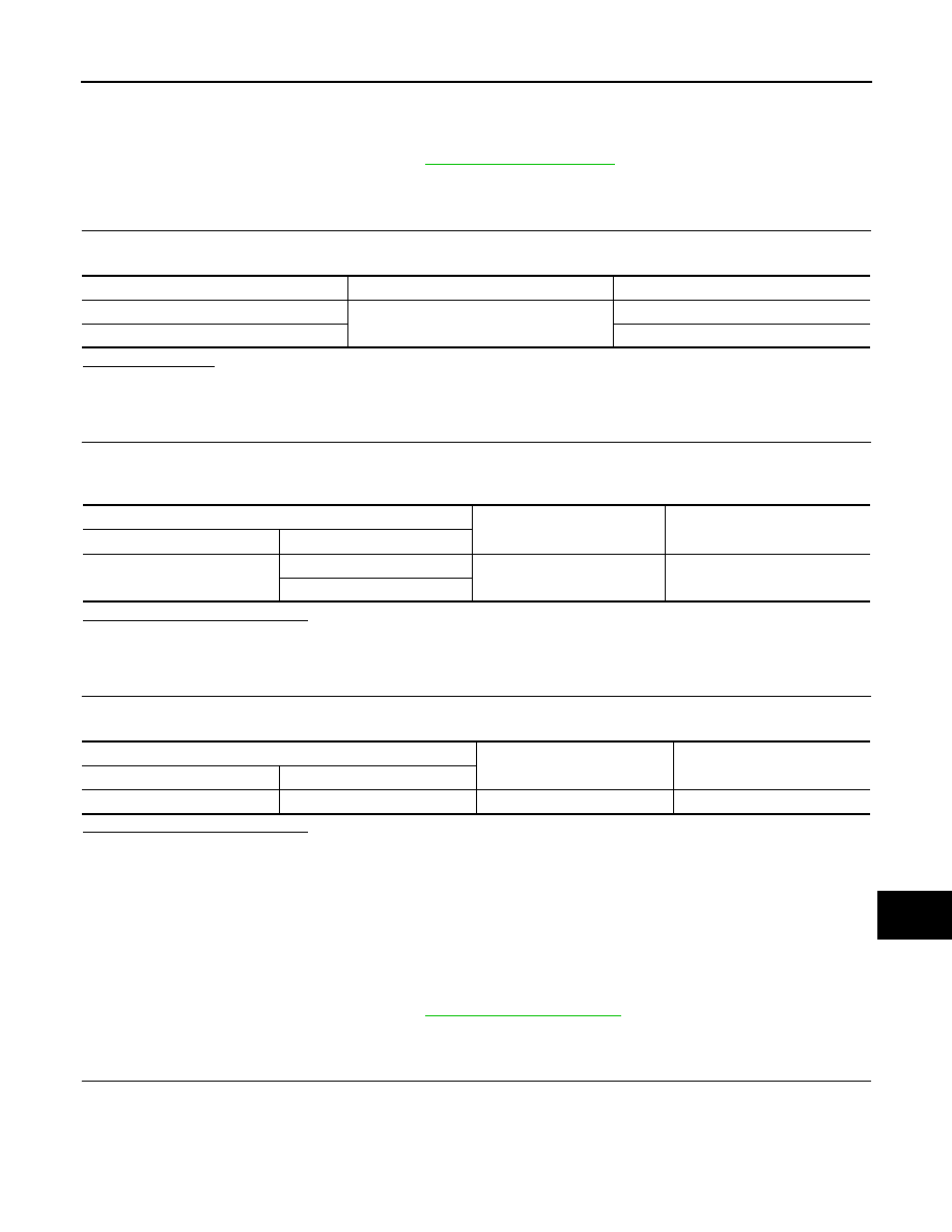
Check that the following fuses and fusible link are not blown.
Terminal No.
Signal name
Fuses and fusible link No.
57
Battery power supply
12 (10A)
70
G (40A)
BCM
Ground
Voltage
Connector
Terminal
M99
57
—
Battery voltage
70
BCM
Ground
Continuity
Connector
Terminal
M99
67
—
Yes