Nissan Versa Note. Manual - part 574


  Index      Nissan     Nissan Versa Note (2014 year) - Service and Repair Manual


Search            


Content   ..  572  573  574  575   ..


Nissan Versa Note. Manual - part 574


MA-32

< PERIODIC MAINTENANCE >

CHASSIS AND BODY MAINTENANCE

GEAR OIL : Refilling

INFOID:0000000009681961

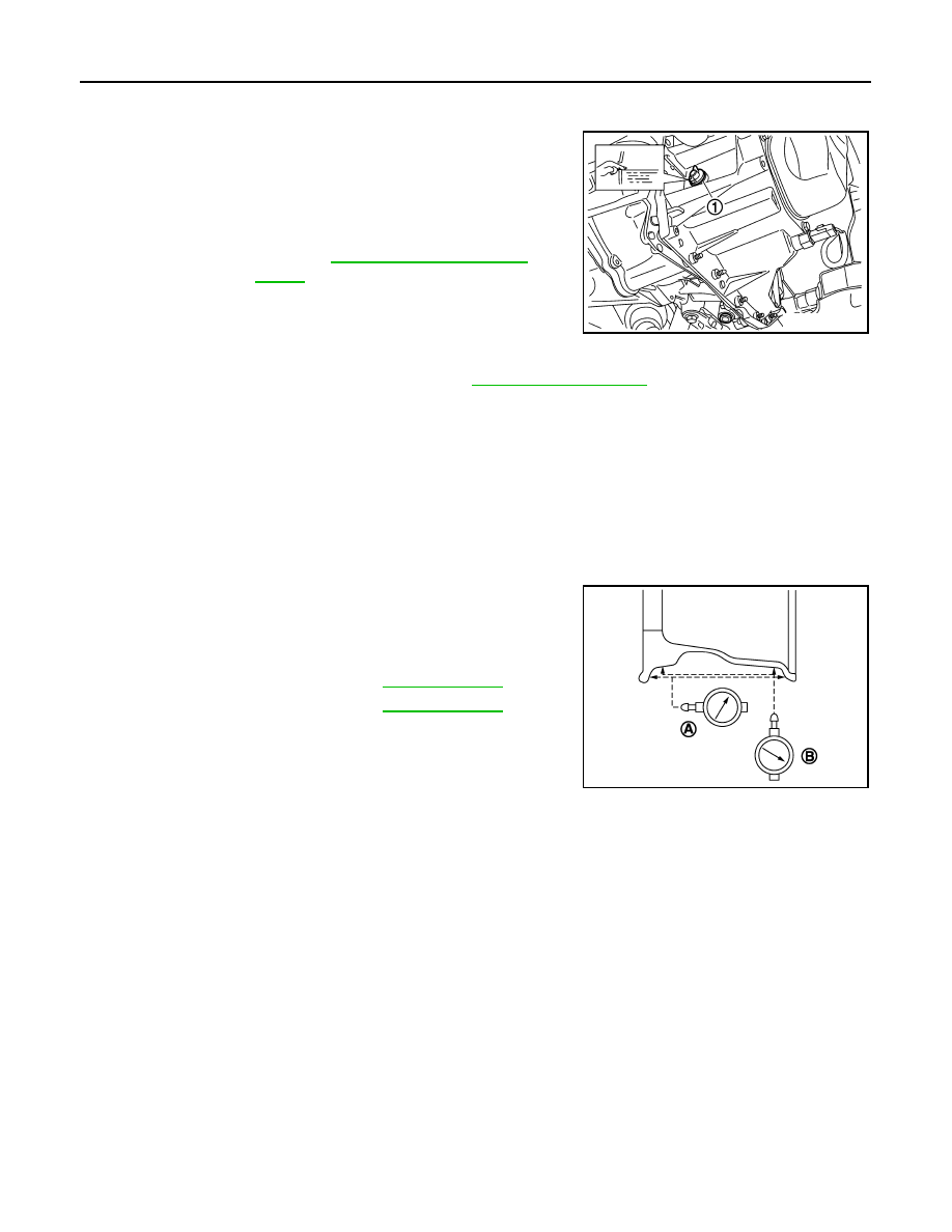
1. Remove filler plug (1) and gasket from transaxle case. 
2. Fill with new gear oil until gear oil level reaches the specified

limit at filler plug hole as shown.

CAUTION:

Do not start engine while checking gear oil level.

3. Install a new gasket on filler plug and then install filler plug to

transaxle case.

CAUTION:

Do not reuse gasket.

4. Tighten filler plug to the specified torque. Refer to 

TM-26, "Exploded View"

.

WHEELS
WHEELS : Inspection

INFOID:0000000009681967

1. Check tires for wear and improper inflation.
2. Check wheels for deformation, cracks and other damage. If deformed, remove wheel and check wheel

runout.

a. Remove tire from wheel and mount wheel on a balancer machine.
b. Set dial indicator as shown.
c.

Check runout, if runout value exceeds the limit, replace wheel.

WHEELS : Adjustment

INFOID:0000000009681968

BALANCING WHEELS (ADHESIVE WEIGHT TYPE)

Preparation Before Adjustment

Remove inner and outer balance weights from the wheel and tire. Using releasing agent, remove double-faced

adhesive tape from the wheel and tire.

CAUTION:

• Be careful not to scratch the wheel and tire during removal.

• After removing double-faced adhesive tape, wipe clean all traces of releasing agent from the wheel

and tire.

Wheel Balance Adjustment

CAUTION:

• DO NOT use center hole cone-type clamping machines to hold the wheel during tire removal/installa-

tion or balancing or damage to the wheel paint, cladding or chrome may result. Use only rim-type or

universal lug-type clamping machines to hold the wheel during servicing.

• If a balancer machine has an adhesive weight mode setting, select the adhesive weight mode setting and

skip Step 2 below. If a balancer machine only has the clip-on (rim flange) weight mode setting, follow Step 2

to calculate the correct size adhesive weight.

1. Set wheel and tire on balancer machine using the center hole as a guide. Start the balancer machine.

Oil capacity 
and viscosity

: Refer to 

MA-11, "Fluids and Lubri-

cants"

.

SCIA7119E

Limit
Axial Runout (A)

Refer to 

WT-50, "Wheel"

.

Radial Runout (B)

Refer to 

WT-50, "Wheel"

.

SEIA0737E

CHASSIS AND BODY MAINTENANCE

MA-33

< PERIODIC MAINTENANCE >

C

D

E

F

G

H

I

J

K

L

M

B

MA

N

O

A

2. For balancer machines that only have a clip-on (rim flange) weight mode setting, follow this step to calcu-

late the correct size adhesive weight to use. When inner and outer imbalance values are shown on the

balancer machine indicator, multiply outer imbalance value by 5/3 (1.67) to determine balance weight that

should be used. Select the outer balance weight with a value closest to the calculated value above and

install in to the designated outer position of or at the designated angle in relation to the wheel and tire.

a. Indicated imbalance value 

× 5/3 (1.67) = balance weight to be

installed

Calculation example:

23 g (0.81 oz) 

× 5/3 (1.67) = 38.33 g (1.35 oz) ⇒ 40 g (1.41 oz)

balance weight (closer to calculated balance weight value)

NOTE:

Note that balance weight value must be closer to the calculated

balance weight value.

Example:

37.4 

⇒ 35 g (1.23 oz)

37.5 

⇒ 40 g (1.41 oz)

3. Install balance weight in the position shown.

CAUTION:

• Do not install the inner balance weight before installing

the outer balance weight.

• Before installing the balance weight, be sure to clean the

mating surface of the wheel and tire.

• When installing balance weight (1) to wheel and tire, set it into

the grooved area (A) on the inner wall of the wheel and tire as

shown so that the balance weight center (B) is aligned with the

balancer machine indication position (angle) (C).

CAUTION:

• Always use Genuine NISSAN adhesive balance weights.

• Balance weights are non-reusable; always replace with

new ones.

• Do not install more than three sheets of balance

weights.

4. If calculated balance weight value exceeds 50 g (1.76 oz), install

two balance weight sheets in line with each other as shown.

CAUTION:

Do not install one balance weight sheet on top of another.

5. Start balancer machine again.
6. Install balance weight on inner side of wheel and tire in the bal-

ancer machine indication position (angle).

CAUTION:

Do not install more than two balance weights.

7. Start balancer machine. Make sure that inner and outer residual

imbalance values are 5 g (0.17 oz) each or below.

8. If either residual imbalance value exceeds 5 g (0.17 oz), repeat installation procedures.

SMA054D

JPEIC0040ZZ

Wheel balance

Dynamic (At flange)

Static (At flange)

Maximum allowable im-
balance

Refer to 

WT-50, "Wheel"

.

PEIA0033E

MA-34

< PERIODIC MAINTENANCE >

CHASSIS AND BODY MAINTENANCE

TIRE ROTATION

• Follow the maintenance schedule for tire rotation service intervals.

Refer to 

MA-7, "Introduction of Periodic Maintenance"

.

• Rotate the wheel and tires front to back in the pattern as shown.

• When installing the wheel, tighten wheel nuts to the specified

torque.

WARNING:

• After rotating the tires, check and adjust the tire pressure.

• Retighten the wheel nuts when the vehicle has been driven

for 1,000 km (600 mi) (also in case of a flat tire, etc.).

• Do not include the spare tire when rotating the tires.

CAUTION:

• When installing wheels, tighten them diagonally by dividing the work two to three times in order to

prevent the wheels from developing any distortion.

• Be careful not to tighten the wheel nuts to a torque exceeding specification to prevent strain on the

disc rotor.

• Use Genuine NISSAN wheel nuts.

• Perform the ID registration after tire rotation. Refer to 

WT-22, "Work Procedure"

.

BRAKE FLUID LEVEL AND LEAKS
BRAKE FLUID LEVEL AND LEAKS : Inspection

INFOID:0000000009417535

BRAKE FLUID LEVEL

• Check that the fluid level in the reservoir tank is within the specified

range between the MAX – MIN lines as shown.

• Visually check for any brake fluid leakage around the reservoir

tank.

• Check the brake system for any leakage if the fluid level is

extremely low (lower than MIN).

• Check the brake system for fluid leakage if the warning lamp

remains illuminated even after the parking brake is released.

• Check the reservoir tank for foreign matter (e.g., dust) and oils

other than brake fluid.

BRAKE LINES AND CABLES
BRAKE LINES AND CABLES : Inspection

INFOID:0000000009417536

BRAKE LINES

1. Check brake lines (pipes and hoses) for cracks, deterioration or

other damage. Replace any damaged parts.

2. Check for brake fluid leaks by fully depressing brake pedal while

engine is running.

CAUTION:

Retighten the applicable connection to the specified torque

and repair any abnormal (damaged, worn or deformed) part

if any brake fluid leaks are present.

PARKING BRAKE CABLES

Check parking brake cables for improper attachment, leaks, chafing, abrasions, deterioration, etc.

Wheel nut tightening 
torque

WT-45, "Exploded View"

SMA829C

JPFIA0007ZZ

SBR389C

CHASSIS AND BODY MAINTENANCE

MA-35

< PERIODIC MAINTENANCE >

C

D

E

F

G

H

I

J

K

L

M

B

MA

N

O

A

BRAKE FLUID
BRAKE FLUID : Inspection

INFOID:0000000009681969

BRAKE FLUID LEVEL

• Check that the fluid level in the reservoir tank is within the specified

range between the MAX – MIN lines as shown.

• Visually check for any brake fluid leaks around the reservoir tank.

• Check the brake system for any leaks if the fluid level is extremely

low (lower than MIN).

• Check the brake system for fluid leaks if the warning lamp remains

illuminated even after the parking brake is released.

• Check the reservoir tank for the mixing of foreign matter (e.g. dust)

and oils other than brake fluid.

BRAKE LINE

1. Check brake tubes and hoses for cracks, deterioration or other

damage. Replace any damaged parts.

2. Check for brake fluid leaks by fully depressing brake pedal while

engine is running.

CAUTION:

Retighten the applicable connection to the specified torque

and repair any abnormal (damaged, worn or deformed) part

if any brake fluid leaks are present.

BRAKE FLUID : Draining

INFOID:0000000009681970

CAUTION:

• Do not spill or splash brake fluid on painted surfaces. Brake fluid may seriously damage paint. Wipe

it off immediately and wash with water if it gets on a painted surface.

• Turn the ignition switch OFF and disconnect ABS actuator and electric unit (control unit) or battery

negative terminal before performing work.

1. Connect a vinyl tube to the bleeder valve.
2. Depress the brake pedal and loosen the bleeder valve to gradu-

ally discharge brake fluid.

BRAKE FLUID : Refilling

INFOID:0000000009681971

CAUTION:

• Turn the ignition switch OFF and disconnect ABS actuator and electric unit (control unit) or battery

negative terminal before performing work.

• Do not spill or splash brake fluid on painted surfaces. Brake fluid may seriously damage paint. Wipe

it off immediately and wash with water if it gets on a painted surface.

• Monitor the brake fluid level in the reservoir while performing the air bleeding procedure.

• Always use new brake fluid for refilling. Do not reuse drained brake fluid.

• Do not allow foreign matter (e.g. dust) and oils other than brake fluid to enter the reservoir tank.

JPFIA0007ZZ

SBR389C

BRA0007D


Content   ..  572  573  574  575   ..