Nissan Versa Note. Manual - part 445


  Index      Nissan     Nissan Versa Note (2014 year) - Service and Repair Manual


Search            


Content   ..  443  444  445  446   ..


Nissan Versa Note. Manual - part 445


FRONT WHEEL HUB AND KNUCKLE

FAX-7

< PERIODIC MAINTENANCE >

C

E

F

G

H

I

J

K

L

M

A

B

FAX

N

O

P

PERIODIC MAINTENANCE

FRONT WHEEL HUB AND KNUCKLE

Inspection

INFOID:0000000009521209

COMPONENT PART

• Check that the mounting conditions (looseness, backlash) of each component and component conditions

(wear, damage) are normal.

• Check the axle and suspension parts for excessive play, weary or damage.

• Shake each front wheel to check for excessive play.

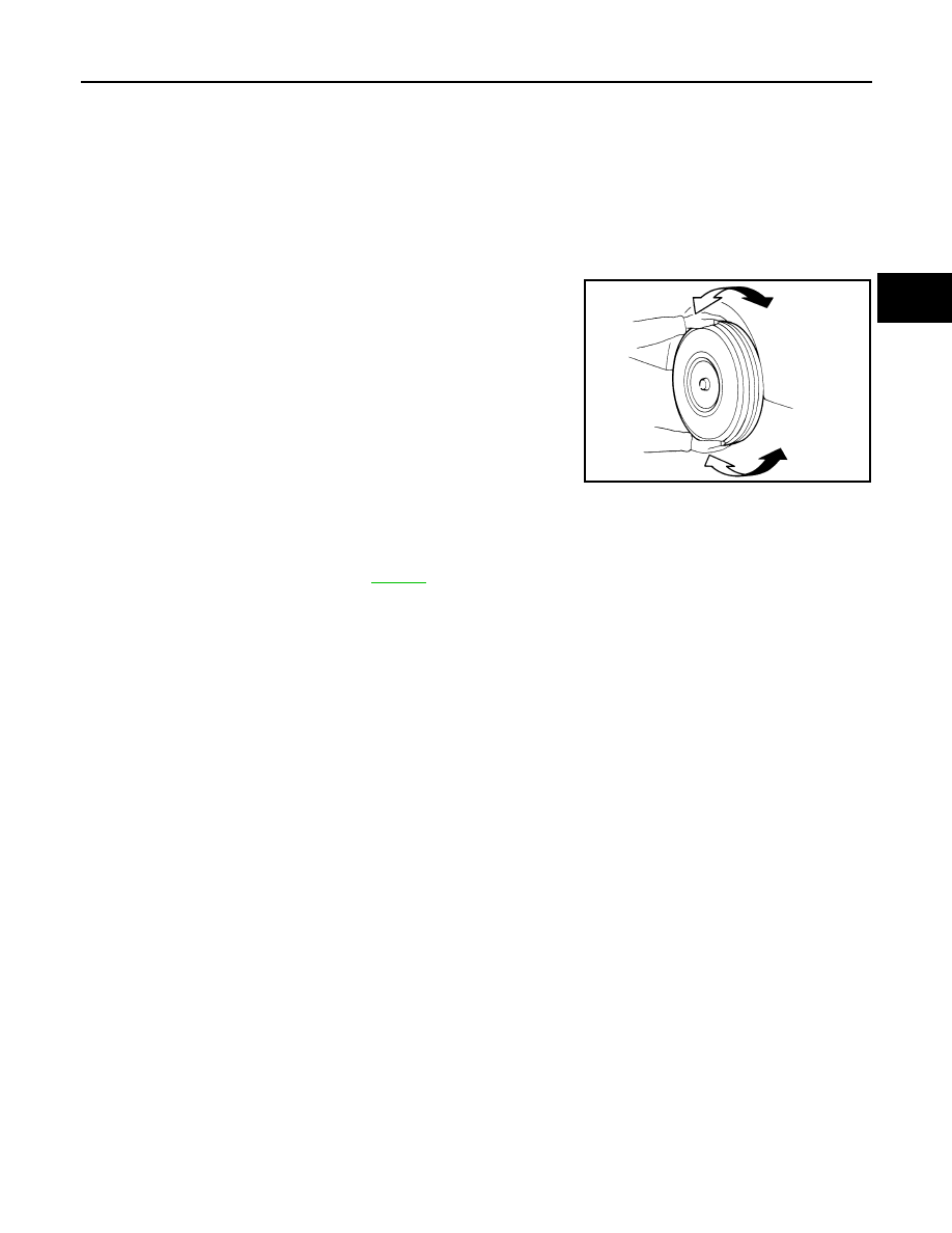
FRONT WHEEL BEARING INSPECTION

Check the following items, and replace the part if necessary.

• Move the wheel bearing in the axial direction by hand. Make sure there is no looseness in the wheel bearing.

• Rotate the wheel bearing and make sure there is no unusual noise or other irregular conditions. If there are

any irregular conditions, replace wheel bearing.

SMA525A

Axial end play

: Refer to 

FAX-27

.

FAX-8

< PERIODIC MAINTENANCE >

FRONT DRIVE SHAFT

FRONT DRIVE SHAFT

Inspection

INFOID:0000000009521210

Check the following items, and replace the part if necessary.

• Check drive shaft mounting point and joint for looseness and other damage.

CAUTION:

Replace entire drive shaft when noise or vibration occurs from drive shaft.

• Check boot for cracks and other damage.

FRONT WHEEL HUB AND KNUCKLE

FAX-9

< REMOVAL AND INSTALLATION >

C

E

F

G

H

I

J

K

L

M

A

B

FAX

N

O

P

REMOVAL AND INSTALLATION

FRONT WHEEL HUB AND KNUCKLE

Exploded View

INFOID:0000000008969169

Removal and Installation

INFOID:0000000009521203

REMOVAL

1. Remove the wheel and tire using power tool. Refer to 

WT-45, "Removal and Installation"

.

2. Remove wheel sensor and sensor harness. Refer to 

BRC-105, "FRONT WHEEL SENSOR : Removal and

Installation"

.

3. Remove brake caliper using power tool, leaving brake hose connected. Reposition brake caliper aside

with wire. Refer to 

BR-36, "BRAKE CALIPER ASSEMBLY : Removal and Installation"

.

NOTE:

Avoid depressing brake pedal while brake caliper is removed.

4. Put matching marks on disc brake rotor and wheel hub, then remove disc brake rotor.

CAUTION:

• Use paint for matching parts. Do not damage the disc brake rotor or wheel hub.

• Do not drop disc rotor.

5. Remove and discard cotter pin, and then loosen wheel hub lock nut, using Tool.

6. Separate the drive shaft from the wheel hub by lightly tapping the end of the drive shaft using a suitable

tool and a wood block.

NOTE:

1.

Steering knuckle

2.

Splash guard

3.

Wheel bearing

4.

Snap ring

5.

Wheel stud

6.

Wheel hub

7.

Disc brake rotor

8.

Wheel hub lock nut

9.

Cotter pin

AWDIA1108ZZ

Tool number : KV40104000 ( — )

FAX-10

< REMOVAL AND INSTALLATION >

FRONT WHEEL HUB AND KNUCKLE

Use suitable puller if wheel hub and drive shaft cannot be separated after performing the above proce-

dure.

7. Remove wheel hub lock nut.
8. Remove the nut and separate the steering outer socket from steering knuckle. Refer to 

ST-14, "Exploded

View"

.

9. Remove the nuts and bolts, then separate the steering knuckle from strut. Refer to 

FAX-9, "Removal and

Installation"

.

10. Suspend the drive shaft with suitable wire. 

CAUTION:

• Do not place drive shaft joint at an extreme angle. Also be careful not to overextend slide joint.

• Do not allow drive shaft to hang down without support for joint sub-assembly, shaft and the

other parts.

11. Remove transverse link outer nut and bolt. Remove steering knuckle from transverse link.
12. If necessary, remove wheel studs (1) from wheel hub using the

suitable tool (A). 

CAUTION:

• Remove stud only when necessary.

• Do not hammer the wheel stud or damage to the wheel

bearing may occur.

• Press the wheel stud straight out to avoid damaging the

stud.

INSTALLATION

Installation is in the reverse order of the removal.

CAUTION:

• Do not reuse the transverse link outer nut.

• Do not damage the wheel bearing seal. If damage has occurred, replace wheel bearing.

• Do not allow paint to adhere to the wheel bearing seal.

• Check each mating surface for water and foreign matter. If there is any water or foreign matter, clean

the mounting surface.

• Position the stud (1) to the wheel hub flange. Place a washer (A)

and nut (B) on the opposite end of the stud. Tighten to press the

stud into the wheel hub flange.

CAUTION:

• Check that no clearance exists between wheel hub and

wheel stud after installation. 

• Do not reuse wheel stud.

• Clean the mating surfaces of wheel hub lock nut and wheel hub.

CAUTION:

Do not apply lubricating oil to the mating surface of the wheel hub lock nut and the wheel hub.

JPDIF0299ZZ

JPDIF0300ZZ


Content   ..  443  444  445  446   ..