Nissan Versa Note. Manual - part 446


  Index      Nissan     Nissan Versa Note (2014 year) - Service and Repair Manual


Search            


Content   ..  444  445  446  447   ..


Nissan Versa Note. Manual - part 446


FRONT WHEEL HUB AND KNUCKLE

FAX-11

< REMOVAL AND INSTALLATION >

C

E

F

G

H

I

J

K

L

M

A

B

FAX

N

O

P

• Clean the mating surfaces of drive shaft, wheel hub, and wheel

bearing. Apply Molykote M77 to surface (A) of joint sub-assembly.

CAUTION:

Apply Molykote M77 to cover entire flat surface of joint sub-

assembly.

NOTE:

Always check with the Parts Department for the latest parts infor-

mation.

• When reusing disc rotor, align the matching marks during removal.

• When installing a cotter pin, securely bend the cotter pin to prevent rattles.

CAUTION:

Do not reuse cotter pin.

Disassembly and Assembly

INFOID:0000000009521204

DISASSEMBLY

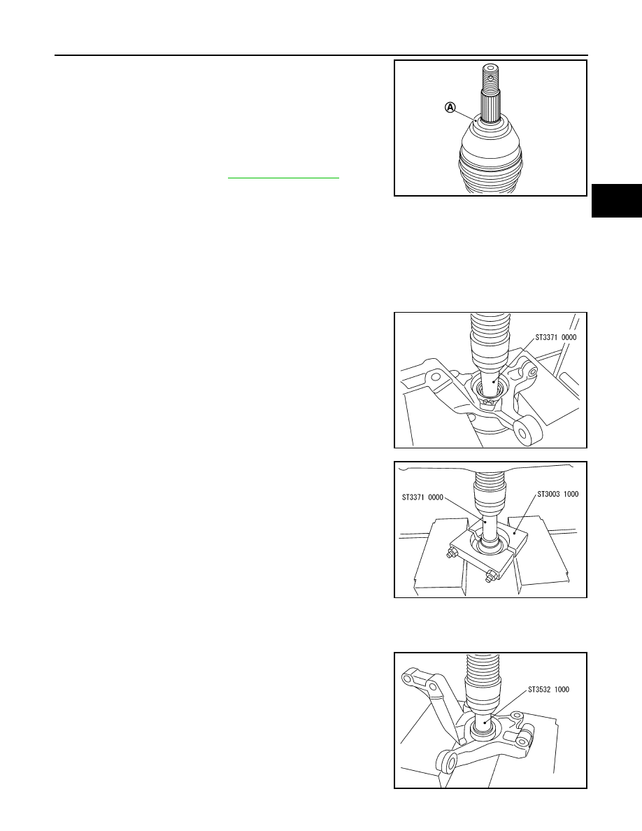
1. Remove wheel hub using Tool.

2. Remove splash guard from steering knuckle.

3. Remove wheel bearing inner race (outer side) from wheel hub

using Tools.

4. Remove snap ring from steering knuckle using suitable tool.

CAUTION:

Do not damage steering knuckle.

5. Remove wheel bearing from steering knuckle using Tool.

Molykote M77 quantity : 

FAX-27, "Drive Shaft"

JSDIA2844ZZ

Tool number : ST33710000 ( — )

SDIA0758J

Tool number : ST33710000 ( — )
Tool number : ST30031000 ( — )

SDIA0759J

Tool number : ST35321000 ( — )

SDIA0760J

FAX-12

< REMOVAL AND INSTALLATION >

FRONT WHEEL HUB AND KNUCKLE

ASSEMBLY

1. Install wheel bearing to steering knuckle using the Tool (A) and a

suitable tool (B).

CAUTION:

• Do not reuse wheel bearing.

• Do not apply a cleaning agent or anticorrosive to the

mounting surfaces of the wheel bearing and steering

knuckle.

• Install wheel bearing with the wheel sensor rotor rubber

part (C) faced to the steering knuckle inner side.

• The wheel sensor rotor of the wheel bearing must be kept

free of foreign matter.

• The press-fit load must be applied to the wheel bearing outer race and the steering knuckle.

• Do not apply press-fit load to the wheel bearing inner race, the seal (C) on the rubber surface

side (wheel sensor rotor side), and the seal (D) on the metallic surface side. If a press-fit load is

applied, the wheel bearing must be replaced with a new one.

2. Install snap ring to steering knuckle.

CAUTION:

• Do not damage the wheel bearing seal.

• The snap ring must be installed evenly into the groove.

3. Press splash guard (1) into the steering knuckle using suitable

tools (A and B).

CAUTION:

Do not reuse splash guard.

4. Install wheel hub using Tools.

CAUTION:

• Do not apply lubricating oil to the press-fit surface of the

wheel hub bearing.

• Set wheel hub and wheel bearing horizontally and insert

them vertically.

• The press-fit load must be applied to the wheel hub and

the wheel bearing inner race.

• Do not apply press-fit load to the steering knuckle and the wheel bearing, the seal. If a press-fit

load is applied, the wheel bearing must be replaced with a new one.

• Apply a press-fit load and maintain the loaded state for 30 seconds.

• If the inserted wheel hub is removed again, the wheel bearing must be replaced with a new one.

Tool number : ST35271000 ( — )

Wheel bearing 
press-fit load

: Refer to 

FAX-27, "Wheel 

Bearing"

JPDIF0306ZZ

JSDIA2728ZZ

Tool number (A) : ST33061000 ( — )
Tool number (B) : ST35321000 ( — )

Wheel bearing 
press-fit load

: Refer to 

FAX-27, "Wheel 

Bearing"

JPDIF0284ZZ

FRONT WHEEL HUB AND KNUCKLE

FAX-13

< REMOVAL AND INSTALLATION >

C

E

F

G

H

I

J

K

L

M

A

B

FAX

N

O

P

Inspection

INFOID:0000000009521205

INSPECTION AFTER REMOVAL

Check the following items, and replace the part if necessary.

• Check components for deformation, cracks, and other damage.

• Check boots of transverse link and steering outer socket ball joint for breakage, axial end play, and swing

torque. Refer to 

FSU-10, "Inspection"

 and 

FSU-20, "Ball Joint"

.

INSPECTION AFTER DISASSEMBLY

Wheel Hub

• Check wheel hub for cracks (with magnetic exploration or dye testing). Replace if necessary.

Steering Knuckle

• Check steering knuckle for deformation, cracks, and other damage. Replace if any non-standard conditions

are found.

Snap Rings

• Check snap ring for wear or cracks. Replace if necessary.

INSPECTION AFTER ASSEMBLY

Check wheel bearing rotating torque as per the following instructions.

NOTE:

The adequacy of turning torque can be judged from a measurement value by a spring balancer.
1. For a proper fit of the bearing, turn the wheel hub clockwise and counterclockwise, respectively, 10 times

or more with a press-fit load applied.

2. Set a spring balance on strut mounting hole (upper). Measure

rotating torque at an rpm of 8 - 12 rpm.

• If the turning torque cannot be obtained by the above method,

measure the torque, according to the instructions below.

- Install drive shaft and tighten the hub lock nut to the specified

torque. Rotate the wheel hub to fit properly.

- Set a spring balancer to the hub bolt and measure turning torque

at turning speeds of 8 to 12 rpm.

INSPECTION BEFORE INSTALLATION

Check wheel sensor rotor for foreign matter. Clean the rotor, if necessary.

INSPECTION AFTER INSTALLATION

1. Check wheel sensor harness to be sure the connectors are fully seated. Refer to 

BRC-105, "FRONT

WHEEL SENSOR : Removal and Installation"

.

2. Check the wheel alignment. Refer to 

FSU-7, "Inspection"

.

Wheel bearing 
press-fit load

: Refer to 

FAX-27, "Wheel 

Bearing"

Rotating torque : Refer to 

FAX-27, "Wheel Bearing"

.

Spring balance 
measurement

: Refer to 

FAX-27, "Wheel Bearing"

.

Rotating torque : Refer to

FAX-27, "Wheel Bearing"

Spring balance 
measurement

: Refer to 

FAX-27, "Wheel Bearing"

SDIA0762J

FAX-14

< REMOVAL AND INSTALLATION >

FRONT DRIVE SHAFT BOOT

FRONT DRIVE SHAFT BOOT

Exploded View

INFOID:0000000008969173

(LH)

(RH)

WHEEL SIDE

JPDIF0266ZZ

1.

Circular clip

2.

Dust shield

3.

Slide joint housing

4.

Snap ring

5.

Spider assembly

6.

Boot band

7.

Boot

8.

Shaft

9.

Damper band

10. Dynamic damper

11. Circular clip

12.

Joint sub-assembly

Wheel side

JPDIF0269ZZ

1.

Circular clip

2.

Dust shield

3.

Slide joint housing

4.

Snap ring

5.

Spider assembly

6.

Boot band

7.

Boot

8.

Shaft

9.

Damper Band

10.

Dynamic damper

11.

Circular clip

12.

Joint sub-assembly

Wheel side


Content   ..  444  445  446  447   ..