Nissan Versa Note. Manual - part 383
EM-48
< REMOVAL AND INSTALLATION >
[HR16DE]
ROCKER COVER
ROCKER COVER
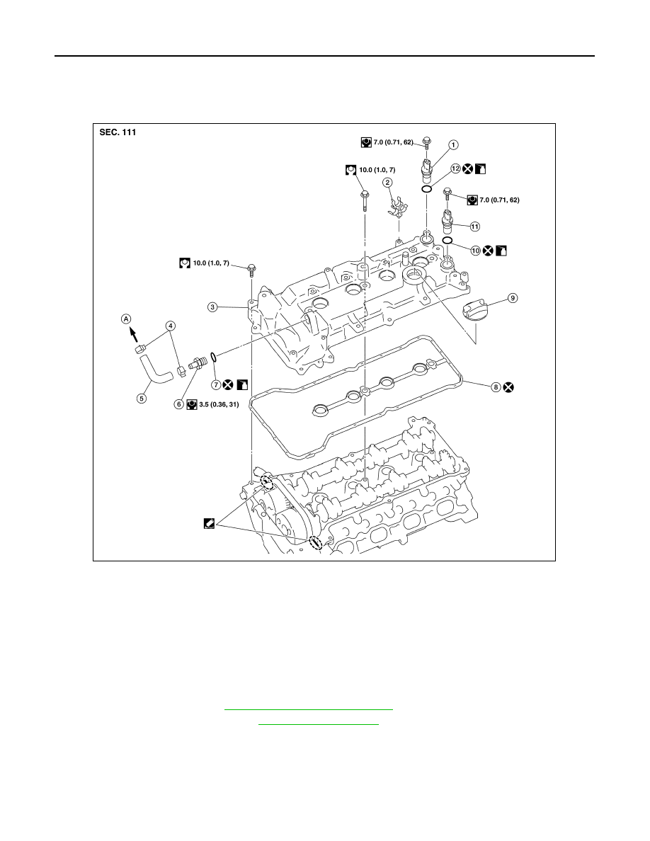
Exploded View
INFOID:0000000009444732
Removal and Installation
INFOID:0000000009444733
REMOVAL
1. Remove ignition coil. Refer to
EM-47, "Removal and Installation"
.
2. Remove fuel tube protector. Refer to
.
3. Remove PCV hose from rocker cover.
4. Remove PCV valve (if necessary).
5. Remove rocker cover.
1.
Exhaust camshaft position sensor
2.
Clip
3.
Rocker cover
4.
Clamp
5.
Hose
6.
PCV valve
7.
O-ring
8.
Rocker cover gasket
9.
Oil filler cap
10.
O-ring
11. Intake camshaft position sensor
12.
O-ring
A.
To intake manifold
AWBIA1604ZZ