Nissan Versa Note. Manual - part 350


  Index      Nissan     Nissan Versa Note (2014 year) - Service and Repair Manual


Search            


Content   ..  348  349  350  351   ..


Nissan Versa Note. Manual - part 350


EC-382

< DTC/CIRCUIT DIAGNOSIS >

[HR16DE]

P1564 ASCD STEERING SWITCH

 Without CONSULT

1. Turn ignition switch ON.

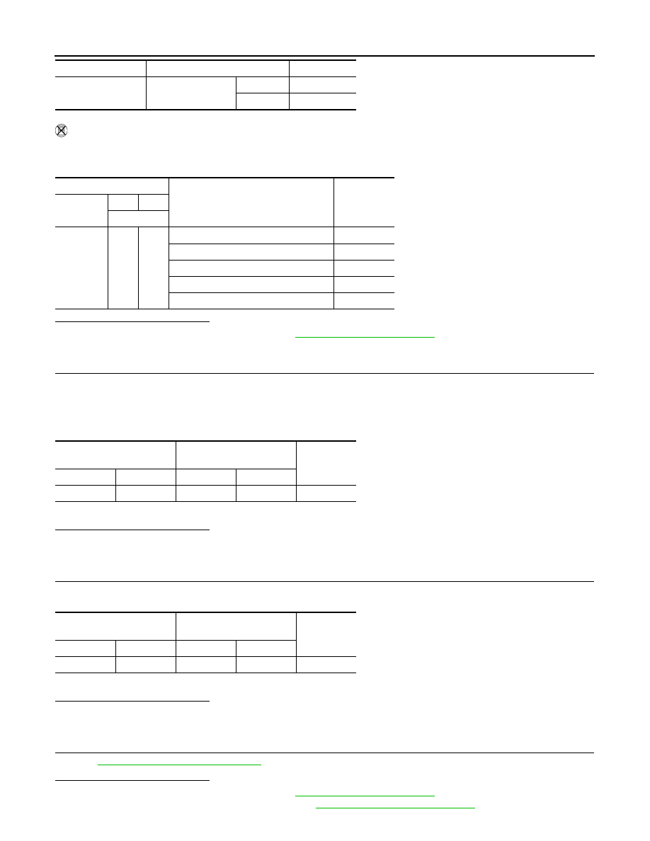
2. Check the voltage between ECM harness connector terminals.

Is the inspection result normal?

YES

>> Check intermittent incident. Refer to 

GI-41, "Intermittent Incident"

.

NO

>> GO TO 2.

2.

CHECK ASCD STEERING SWITCH GROUND CIRCUIT

1. Turn ignition switch OFF.

2. Disconnect ECM harness connector.

3. Disconnect combination switch (spiral cable) harness connector.

4. Check the continuity between combination switch (spiral cable) and ECM harness connector.

5. Also check harness for short to ground and to power.
Is the inspection result normal?

YES

>> GO TO 3.

NO

>> Repair or replace error-detected parts.

3.

CHECK ASCD STEERING SWITCH INPUT SIGNAL CIRCUIT

1. Check the continuity between ECM harness connector and combination switch.

2. Also check harness for short to ground and to power.
Is the inspection result normal?

YES

>> GO TO 4.

NO

>> Repair or replace error-detected parts.

4.

CHECK ASCD STEERING SWITCH

Refer to 

EC-383, "Component Inspection"

.

Is the inspection result normal?

YES

>> Check intermittent incident. Refer to 

GI-41, "Intermittent Incident"

.

NO

>> Replace ASCD steering switch. Refer to 

ST-8, "Removal and Installation"

.

SET SW

COAST/SET switch

Pressed

ON

Released

OFF

Monitor item

Condition

Indication

ECM

Condition

Voltage

(Approx.)

Connector

+

-

Terminal

E16

94

95

MAIN switch: Pressed

0 V

CANCEL switch: Pressed

1 V

COAST/SET switch: Pressed

2 V

ACCEL/RES switch: Pressed

3 V

All ASCD steering switches: Released

4 V

Combination switch

(Spiral cable)

ECM

Continuity

Connector

Terminal

Connector

Terminal

M30

32

E16

95

Existed

Combination switch

(Spiral cable)

ECM

Continuity

Connector

Terminal

Connector

Terminal

M30

25

E16

94

Existed

P1564 ASCD STEERING SWITCH

EC-383

< DTC/CIRCUIT DIAGNOSIS >

[HR16DE]

C

D

E

F

G

H

I

J

K

L

M

A

EC

N

P

O

Component Inspection

INFOID:0000000009020875

1.

CHECK ASCD STEERING SWITCH

1. Disconnect combination switch (spiral cable) harness connector.

2. Check the resistance between combination switch harness connector terminals as per the following condi-

tions.

Is the inspection result normal?

YES

>> INSPECTION END

NO

>> Replace ASCD steering switch. Refer to 

ST-8, "Removal and Installation"

.

Combination switch

(Spiral cable)

Condition

Resistance

(Approx.)

Connector

+

Terminals

M88

13

16

MAIN switch: Pressed

CANCEL switch: Pressed

250 

COAST/SET switch: Pressed

660 

ACCEL/RES switch: Pressed

1,480 

All ASCD steering switches: Released

4,000 

EC-384

< DTC/CIRCUIT DIAGNOSIS >

[HR16DE]

P1572 ASCD BRAKE SWITCH

P1572 ASCD BRAKE SWITCH

DTC Logic

INFOID:0000000009020876

DTC DETECTION LOGIC

NOTE:

• If DTC P1572 is displayed with DTC P0605, first perform the trouble diagnosis for DTC P0605. Refer

to 

EC-349, "DTC Logic"

.

• This self-diagnosis has the one trip detection logic. When malfunction A is detected, DTC is not

stored in ECM memory. And in that case, 1st trip DTC and 1st trip freeze frame data are displayed.

1st trip DTC is erased when ignition switch OFF. And even when malfunction A is detected in two

consecutive trips, DTC is not stored in ECM memory.

DTC CONFIRMATION PROCEDURE

1.

PRECONDITIONING

If DTC Confirmation Procedure has been previously conducted, always perform the following procedure

before conducting the next test.

1. Turn ignition switch OFF and wait at least 10 seconds.

2. Turn ignition switch ON.

3. Turn ignition switch OFF and wait at least 10 seconds.

NOTE:

Procedure for malfunction B is not described here. It takes extremely long time to complete procedure for mal-

function B. By performing procedure for malfunction A, the incident that causes malfunction B can be

detected.

>> GO TO 2.

2.

PERFORM DTC CONFIRMATION PROCEDURE FOR MALFUNCTION A

1. Start engine.

2. Press MAIN switch and make sure that CRUISE indicator is displayed in combination meter.

3. Drive the vehicle for at least 5 consecutive seconds as per the following conditions.

CAUTION:

Always drive vehicle at a safe speed.

NOTE:

This procedure may be conducted with the drive wheels lifted in the shop or by driving the vehicle.

If a road test is expected to be easier, it is unnecessary to lift the vehicle.

4. Check DTC.
Is DTC detected?

YES

>> Proceed to 

EC-389, "Diagnosis Procedure"

.

NO

>> GO TO 3.

3.

PERFORM DTC CONFIRMATION PROCEDURE FOR MALFUNCTION B

1. Drive the vehicle for at least 5 consecutive seconds as per the following conditions.

CAUTION:

DTC No.

CONSULT screen terms

(Trouble diagnosis content)

DTC detecting condition

Possible cause

P1572

ASCD BRAKE SW
(ASCD brake switch)

A)

When the vehicle speed is above 30 km/h 
(19 MPH), ON signals from the stop lamp 
switch and the ASCD brake switch are 
sent to the ECM at the same time.

• Harness or connectors

(Stop lamp switch circuit is shorted.)
(ASCD brake switch circuit is shorted.)

• Stop lamp switch
• ASCD brake switch
• Incorrect stop lamp switch installation
• Incorrect ASCD brake switch installation
• ECM

B)

ASCD brake switch signal is not sent to 
ECM for extremely long time while the ve-
hicle is driving.

Vehicle speed

More than 30 km/h (19 mph)

Selector lever

Suitable position 

P1572 ASCD BRAKE SWITCH

EC-385

< DTC/CIRCUIT DIAGNOSIS >

[HR16DE]

C

D

E

F

G

H

I

J

K

L

M

A

EC

N

P

O

Always drive vehicle at a safe speed.

NOTE:

This procedure may be conducted with the drive wheels lifted in the shop or by driving the vehicle.

If a road test is expected to be easier, it is unnecessary to lift the vehicle.

2. Check DTC.
Is DTC detected?

YES

>> Proceed to 

EC-389, "Diagnosis Procedure"

.

NO

>> INSPECTION END

Diagnosis Procedure

INFOID:0000000009020877

1.

CHECK OVERALL FUNCTION-I

With CONSULT

1. Turn ignition switch ON.

2. Select “BRAKE SW1” in “DATA MONITOR” mode of “ENGINE” using CONSULT.

3. Check “BRAKE SW1” indication as per the following conditions.

Without CONSULT

1. Turn ignition switch ON.

2. Check the voltage between ECM harness connector terminals as per the following.

Is the inspection result normal?

YES

>> GO TO 2.

NO

>> GO TO 3.

2.

CHECK OVERALL FUNCTION-II

With CONSULT

Select “BRAKE SW2” and check indication as per the following conditions.

Without CONSULT

Check the voltage between ECM harness connector terminals as per the following conditions.

Vehicle speed

More than 30 km/h (19 mph)

Selector lever

Suitable position 

Driving location

Depress the brake pedal for more than five seconds so as 
not to come off from the above-mentioned vehicle speed.

Monitor item

Condition

Indication

BRAKE SW1

Brake pedal

Slightly depressed

OFF

Fully released

ON

ECM

Condition

Voltage

(Approx.)

Connector

+

Terminal

E16

100

108

Brake pedal

Slightly depressed

0 V

Fully released

Battery voltage

Monitor item

Condition

Indication

BRAKE SW2

Brake pedal

Slightly depressed

ON

Fully released

OFF


Content   ..  348  349  350  351   ..