Nissan Versa Note. Manual - part 351
EC-386
< DTC/CIRCUIT DIAGNOSIS >
[HR16DE]
P1572 ASCD BRAKE SWITCH
Is the inspection result normal?
YES
>> Check intermittent incident. Refer to
GI-41, "Intermittent Incident"
.
NO
>> GO TO 6.
3.
CHECK ASCD BRAKE SWITCH POWER SUPPLY
1. Turn ignition switch OFF.
2. Disconnect ASCD brake switch harness connector.
3. Turn ignition switch ON.
4. Check the voltage between ASCD brake switch harness connector and ground.
Is the inspection result normal?
YES
>> GO TO 4.
NO
>> Perform the trouble diagnosis for power supply circuit.
4.
CHECK ASCD BRAKE SWITCH INPUT SIGNAL CIRCUIT
1. Turn ignition switch OFF.
2. Disconnect ECM harness connector.
3. Check the continuity between ASCD brake switch harness connector and ECM harness connector.
4. Also check harness for short to ground and to power.
Is the inspection result normal?
YES
>> GO TO 5.
NO
>> Repair or replace error-detected parts.
5.
CHECK ASCD BRAKE SWITCH
Check the ASCD brake switch. Refer to
EC-426, "Component Inspection (ASCD Brake Switch)"
Is the inspection result normal?
YES
>> Check intermittent incident. Refer to
GI-41, "Intermittent Incident"
.
NO
>> Replace ASCD brake switch. Refer to
.
6.
CHECK STOP LAMP SWITCH POWER SUPPLY CIRCUIT
1. Turn ignition switch OFF.
2. Disconnect stop lamp switch harness connector.
3. Check the voltage between stop lamp switch harness connector and ground.
Is the inspection result normal?
YES
>> GO TO 7.
NO
>> Perform the trouble diagnosis for power supply circuit.
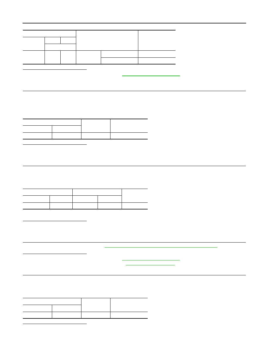
ECM
Condition
Voltage
(Approx.)
Connector
+
–
Terminal
E16
99
108
Brake pedal
Slightly depressed
Battery voltage
Fully released
0 V
ASCD brake switch
Ground
Voltage
Connector
Terminal
E36
1
Ground
Battery voltage
ASCD brake switch
ECM
Continuity
Connector
Terminal
Connector
Terminal
E36
2
E16
100
Existed
Stop lamp switch
Ground
Voltage
Connector
Terminal
E13
1
Ground
Battery voltage