Nissan Versa Note. Manual - part 299


  Index      Nissan     Nissan Versa Note (2014 year) - Service and Repair Manual


Search            


Content   ..  297  298  299  300   ..


Nissan Versa Note. Manual - part 299


EC-178

< DTC/CIRCUIT DIAGNOSIS >

[HR16DE]

P0075 IVT CONTROL SOLENOID VALVE

3. Check the continuity between intake valve timing control solenoid valve harness connector and ECM har-

ness connector.

4. Also check harness for short to ground and short to power. 
Is the inspection result normal?

YES

>> GO TO 4.

NO

>> Repair open circuit or short to ground or short to power in harness or connectors.

4.

CHECK INTAKE VALVE TIMING CONTROL SOLENOID VALVE

Refer to 

EC-178, "Component Inspection"

.

Is the inspection result normal?

YES

>> GO TO 5.

NO

>> Replace intake valve timing control solenoid valve. Refer to 

EM-60, "Exploded View"

.

5.

CHECK INTERMITTENT INCIDENT

Refer to 

GI-41, "Intermittent Incident"

.

>> INSPECTION END

Component Inspection

INFOID:0000000009020692

1.

CHECK INTAKE VALVE TIMING CONTROL SOLENOID VALVE-I

1. Turn ignition switch OFF.

2. Disconnect intake valve timing control solenoid valve harness connector.

3. Check resistance between intake valve timing control solenoid valve terminals as follows.

Is the inspection result normal?

YES

>> GO TO 2.

NO

>> Replace intake valve timing control solenoid valve. Refer to 

EM-60, "Exploded View"

2.

CHECK INTAKE VALVE TIMING CONTROL SOLENOID VALVE-II

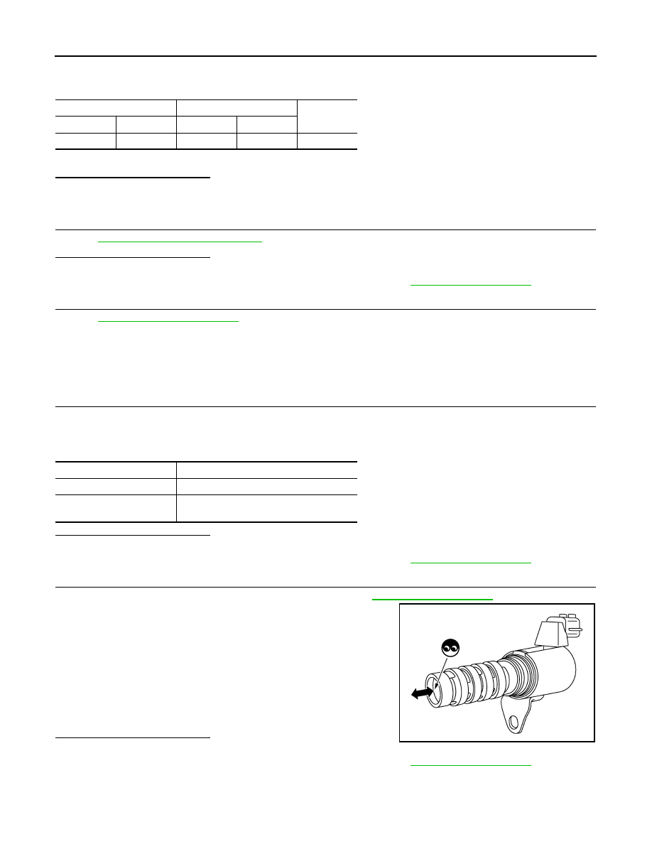
1. Remove intake valve timing control solenoid valve. Refer to 

EM-60, "Exploded View"

.

2. Apply 12 V between intake valve timing control solenoid valve

terminals 1 and 2, and then interrupt it. Make sure that the

plunger moves as shown in the figure.

CAUTION:

Do not apply 12 V continuously for 5 seconds or more.

Doing so may result in damage to the coil in intake valve

timing control solenoid valve.

NOTE:

Always replace O-ring when intake valve timing control

solenoid valve is removed.

Is the inspection result normal?

YES

>> INSPECTION END

NO

>> Replace intake valve timing control solenoid valve. Refer to 

EM-60, "Exploded View"

.

IVT control solenoid valve

ECM

Continuity

Connector

Terminal

Connector

Terminal

F23

1

F11

73

Existed

Terminals

Resistance [at 20

°C (68°F)]

1 and 2

7.0 - 7.7 

Ω 

1 or 2 and ground

∞ Ω

(Continuity should not exist)

JMBIA2108ZZ

P0078 EVT CONTROL SOLENOID VALVE

EC-179

< DTC/CIRCUIT DIAGNOSIS >

[HR16DE]

C

D

E

F

G

H

I

J

K

L

M

A

EC

N

P

O

P0078 EVT CONTROL SOLENOID VALVE

DTC Logic

INFOID:0000000009020693

DTC DETECTION LOGIC

DTC CONFIRMATION PROCEDURE

1.

PRECONDITIONING

If DTC Confirmation Procedure has been previously conducted, always perform the following procedure

before conducting the next test.

1. Turn ignition switch OFF and wait at least 10 seconds.

2. Turn ignition switch ON.

3. Turn ignition switch OFF and wait at least 10 seconds.

>> GO TO2.

2.

PERFORM DTC CONFIRMATION PROCEDURE

1. Start engine and let it idle for 5 seconds.

2. Check 1st trip DTC.
Is 1st trip DTC detected?

YES

>> Proceed to 

EC-179, "Diagnosis Procedure"

.

NO

>> INSPECTION END

Diagnosis Procedure

INFOID:0000000009020694

1.

CHECK EXHAUST VALVE TIMING CONTROL SOLENOID VALVE POWER SUPPLY

1. Turn ignition switch OFF.

2. Disconnect exhaust valve timing (EVT) control solenoid valve harness connector.

3. Turn ignition switch ON.

4. Check the voltage between exhaust valve timing control solenoid valve harness connector and ground.

Is the inspection result normal?

YES

>> GO TO 3.

NO

>> GO TO 2.

2.

CHECK EXHAUST VALVE TIMING CONTROL SOLENOID VALVE POWER SUPPLY CIRCUIT

1. Turn ignition switch OFF.

2. Disconnect IPDM E/R harness connector.

3. Check the continuity between EVT control solenoid valve harness connector and IPDM E/R harness con-

nector.

4. Also check harness for short to ground.

DTC No.

CONSULT screen terms

(Trouble diagnosis content)

DTC detecting condition

Possible cause

P0078

EX V/T ACT/CIRC-B1
(Exhaust valve timing control 
solenoid valve circuit)

An improper voltage is sent to the 
ECM through exhaust valve timing 
control solenoid valve.

• Harness or connectors

(Exhaust valve timing control solenoid valve 
circuit is open or shorted.)

• Exhaust valve timing control solenoid valve

EVT control solenoid valve

Ground

Voltage

Connector

Terminal

F32

2

Ground

Battery voltage

EVT control solenoid valve

IPDM E/R

Continuity

Connector

Terminal

Connector

Terminal

F32

2

F42

39

Existed

EC-180

< DTC/CIRCUIT DIAGNOSIS >

[HR16DE]

P0078 EVT CONTROL SOLENOID VALVE

Is the inspection result normal?

YES

>> Perform the trouble diagnosis for power supply circuit.

NO

>> Repair or replace error-detected parts.

3.

CHECK EXHAUST VALVE TIMING CONTROL SOLENOID VALVE GROUND CIRCUIT

1. Turn ignition switch OFF.

2. Disconnect ECM harness connector.

3. Check the continuity between EVT control solenoid valve harness connector and ECM harness connec-

tor.

4. Also check harness for short to ground and to power. 
Is the inspection result normal?

YES

>> GO TO 4.

NO

>> Repair or replace error-detected parts.

4.

CHECK EXHAUST VALVE TIMING CONTROL SOLENOID VALVE

Check the exhaust valve timing control solenoid valve. Refer to 

EC-180, "Component Inspection"

.

Is the inspection result normal?

YES

>> Check intermittent incident. Refer to 

GI-41, "Intermittent Incident"

.

NO

>> Replace exhaust valve timing control solenoid valve. Refer to 

EM-60, "Exploded View"

.

Component Inspection

INFOID:0000000009020695

1.

CHECK EXHAUST VALVE TIMING CONTROL SOLENOID VALVE-I

1. Turn ignition switch OFF.

2. Disconnect exhaust valve timing control solenoid valve harness connector.

3. Check resistance between exhaust valve timing control solenoid valve terminals as per the following.

Is the inspection result normal?

YES

>> GO TO 2.

NO

>> Replace exhaust valve timing control solenoid valve. Refer to 

EM-60, "Exploded View"

.

2.

CHECK EXHAUST VALVE TIMING CONTROL SOLENOID VALVE-II

1. Remove exhaust valve timing control solenoid valve. Refer to 

EM-60, "Exploded View"

.

2. Provide 12 V DC between exhaust valve timing control solenoid

valve terminals 1 and 2, and then interrupt it. Check that the

plunger moves as shown in the figure.

CAUTION:

Do not apply 12 V DC continuously for 5 seconds or more.

Doing so may result in damage to the coil in exhaust valve

timing control solenoid valve.

NOTE:

Always replace O-ring when exhaust valve timing control

solenoid valve is removed.

Is the inspection result normal?

YES

>> INSPECTION END

EVT control solenoid valve

ECM

Continuity

Connector

Terminal

Connector

Terminal

F32

1

F11

77

Existed

Exhaust valve timing control solenoid valve

Resistance

+

Terminal

1

 2

7.0 - 7.7 

Ω [at 20°C (68°F)]

1

Ground

∞ Ω

(Continuity should not exist)

2

JMBIA2108ZZ

P0078 EVT CONTROL SOLENOID VALVE

EC-181

< DTC/CIRCUIT DIAGNOSIS >

[HR16DE]

C

D

E

F

G

H

I

J

K

L

M

A

EC

N

P

O

NO

>> Replace exhaust valve timing control solenoid valve. Refer to 

EM-60, "Exploded View"

.


Content   ..  297  298  299  300   ..