Nissan Versa Note. Manual - part 240


  Index      Nissan     Nissan Versa Note (2014 year) - Service and Repair Manual


Search            


Content   ..  238  239  240  241   ..


Nissan Versa Note. Manual - part 240


HORN FUNCTION

DLK-245

< DTC/CIRCUIT DIAGNOSIS >

[WITHOUT INTELLIGENT KEY SYSTEM]

C

D

E

F

G

H

I

J

L

M

A

B

DLK

N

O

P

HORN FUNCTION

Description

INFOID:0000000009645404

Perform answer-back for each operation with horn.

Component Function Check

INFOID:0000000009645405

1.

CHECK FUNCTION

1. Select HORN in “ACTIVE TEST” mode with CONSULT.

2. Check the horn operation.

Is the operation normal?

YES

>> Inspection End.

NO

>> Refer to 

DLK-245, "Diagnosis Procedure"

.

Diagnosis Procedure

INFOID:0000000009645406

Regarding Wiring Diagram information, refer to 

DLK-209, "Wiring Diagram"

.

1.

CHECK HORN FUNCTION

Check horn function with horn switch.
Does the horn sound?

YES

>> GO TO 2

NO

>> Refer to 

HRN-3, "Wiring Diagram"

.

2.

CHECK HORN RELAY POWER SUPPLY

1. Turn ignition switch ON.

2. Perform “ACTIVE TEST” (“HORN”) with CONSULT.

3. Using an oscilloscope or analog voltmeter to check voltage between IPDM E/R connector and ground.

Is the inspection result normal?

YES

>> Repair or replace open harness between IPDM E/R and horn relay.

NO

>> GO TO 3

3.

CHECK HORN RELAY CIRCUIT

1. Turn ignition switch OFF.

2. Disconnect IPDM E/R and horn relay connector.

3. Check continuity between IPDM E/R harness connector and horn relay harness connector.

4. Check continuity between IPDM E/R harness connector and ground.
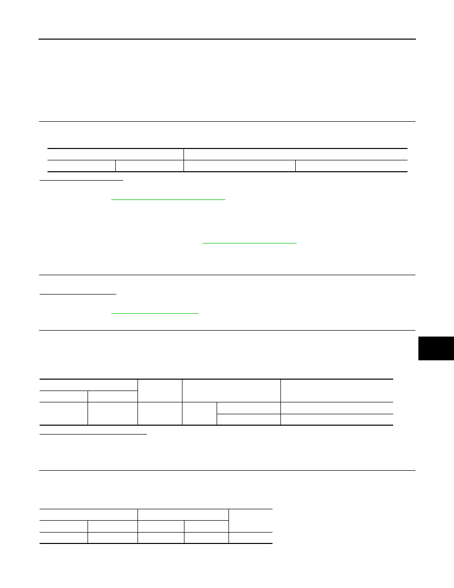
Test item

Description

HORN

ON

Horn relay

ON (for 20 ms)

IPDM E/R

Ground

Test item

Voltage (V)

(Approx.)

Connector

Terminal

E46

73

Ground

HORN

ON

Battery voltage 

→ 0 → Battery voltage

Other than above

Battery voltage

IPDM E/R

Horn relay

Continuity

Connector

Terminal

Connector

Terminal

E46

73

E39

1

Yes

DLK-246

< DTC/CIRCUIT DIAGNOSIS >

[WITHOUT INTELLIGENT KEY SYSTEM]

HORN FUNCTION

Is the inspection result normal?

YES

>> GO TO 4

NO

>> Repair or replace harness.

4.

CHECK INTERMITTENT INCIDENT

Refer to 

GI-41, "Intermittent Incident"

.

Is the inspection result normal?

YES

>> Replace IPDM E/R. Refer to 

PCS-60, "Removal and Installation"

.

NO

>> Repair or replace the malfunctioning part.

IPDM E/R

Ground

Continuity 

Connector

Terminal

E46

73

Ground

No

WARNING CHIME FUNCTION

DLK-247

< DTC/CIRCUIT DIAGNOSIS >

[WITHOUT INTELLIGENT KEY SYSTEM]

C

D

E

F

G

H

I

J

L

M

A

B

DLK

N

O

P

WARNING CHIME FUNCTION

Description

INFOID:0000000009645407

Performs operation method guide and warning with buzzer.

Component Function Check

INFOID:0000000009645408

1.

CHECK FUNCTION

 With CONSULT

1. Check the operation with “BUZZER” in the Active Test.

2. Touch “IGN KEY WARN ALM”, “SEAT BELT WARN TEST”or “LIGHT WARN ALM”on screen.
Is the inspection result normal?

YES

>> Warning buzzer into combination meter is OK.

NO

>> Refer to 

DLK-247, "Diagnosis Procedure"

.

Diagnosis Procedure

INFOID:0000000009645409

1.

CHECK METER BUZZER CIRCUIT

Operate the hazard lights by turning ON the hazard warning switch.
Is the inspection result normal?

YES

>> GO TO 2

NO

>> Replace combination meter. Refer to 

MWI-54, "Removal and Installation"

.

2.

CHECK INTERMITTENT INCIDENT

Refer to 

GI-41, "Intermittent Incident"

.

>> Inspection End.

DLK-248

< DTC/CIRCUIT DIAGNOSIS >

[WITHOUT INTELLIGENT KEY SYSTEM]

HAZARD FUNCTION

HAZARD FUNCTION

Description

INFOID:0000000009645410

Perform answer-back for each operation with number of blinks.

Component Function Check

INFOID:0000000009645411

1.

CHECK FUNCTION

Check hazard warning lamp (“FLASHER”) in Active Test.
Is the inspection result normal?

YES

>> Hazard warning lamp circuit is OK.

NO

>> Refer to 

DLK-248, "Diagnosis Procedure"

.

Diagnosis Procedure

INFOID:0000000009645412

1.

CHECK HAZARD SWITCH CIRCUIT

Operate the hazard lights by turning ON the hazard warning switch.
Is the inspection result normal?

YES

>> GO TO 2

NO

>> Repair or replace hazard warning switch circuit. Refer to 

EXL-104, "Removal and Installation"

.

2.

CHECK INTERMITTENT INCIDENT

Refer to 

GI-41, "Intermittent Incident"

.

>> Inspection End.


Content   ..  238  239  240  241   ..