Nissan Versa Note. Manual - part 167
COOLING FAN
CO-17
< REMOVAL AND INSTALLATION >
[HR16DE]
C
D
E
F
G
H
I
J
K
L
M
A
CO
N
P
O
COOLING FAN
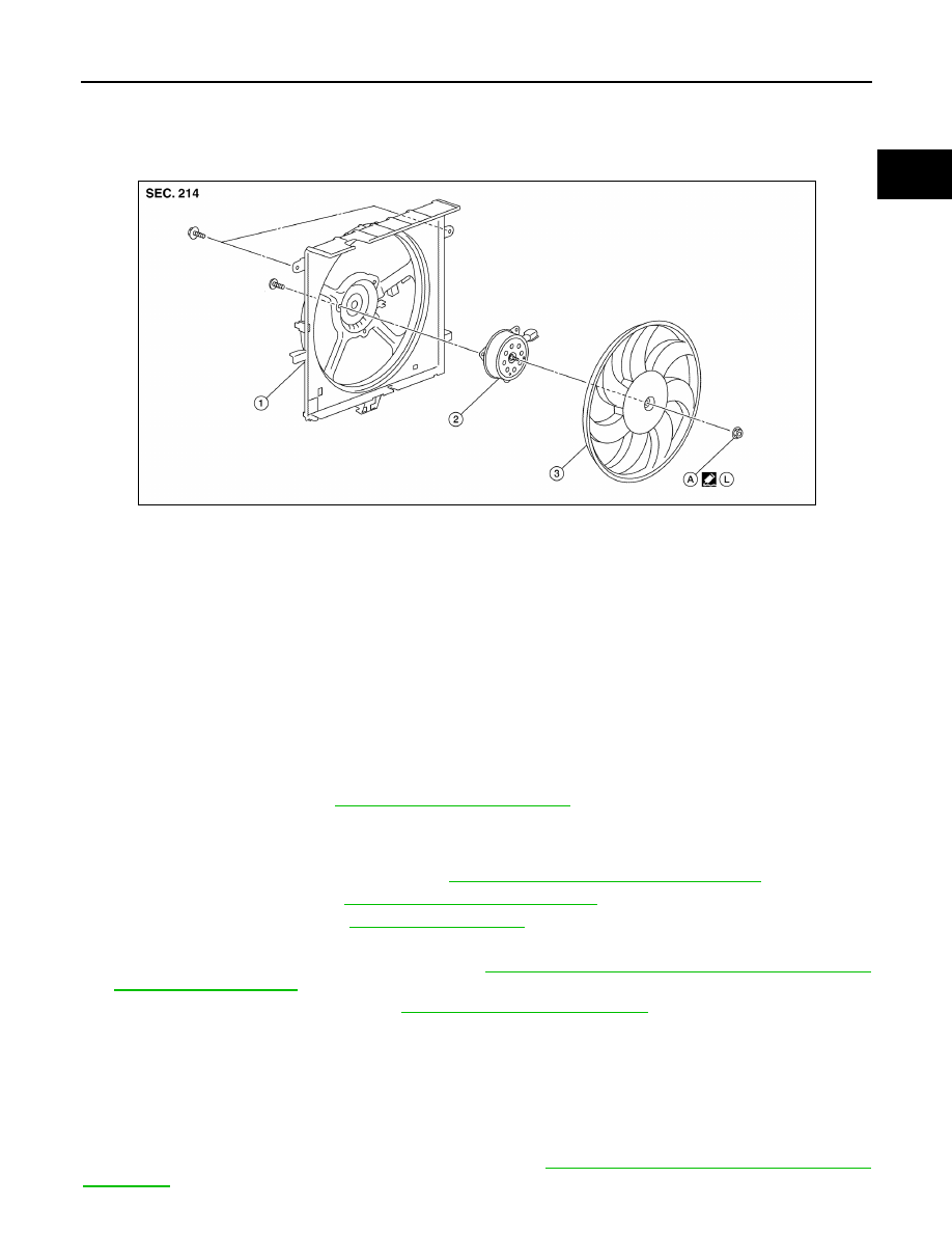
Exploded View
INFOID:0000000009444799
Removal and Installation
INFOID:0000000009444800
REMOVAL
WARNING:
Do not remove the radiator cap when the engine is hot. Serious burns could occur from high-pressure
engine coolant escaping from the radiator. Wrap a thick cloth around the radiator cap. Slowly turn it a
quarter of a turn to release built-up pressure. Carefully remove radiator cap by turning it all the way.
NOTE:
When removing components such as hoses, tubes/lines, etc., cap or plug openings to prevent fluid from spill-
ing.
1. Drain engine coolant. Refer to
CO-8, "Draining Engine Coolant"
.
CAUTION:
• Perform this step when the engine is cold.
• Do not spill engine coolant on drive belt.
2. Disconnect battery negative terminal. Refer to
PG-67, "Removal and Installation (Battery)"
.
3. Remove the front grille. Refer to
EXT-29, "Removal and Installation"
.
4. Remove reservoir tank. Refer to
.
5. Disconnect harness connector from fan motor, and move harness aside.
6. Remove radiator core support (upper). Refer to
DLK-139, "RADIATOR CORE SUPPORT UPPER :
.
7. Remove cooling fan assembly. Refer to
CO-17, "Removal and Installation"
CAUTION:
Be careful not to damage or scratch the radiator.
INSTALLATION
Installation is in the reverse order of removal.
CAUTION:
Only use Genuine NISSAN parts for the fan shroud bolt.
NOTE:
Cooling fan assembly is controlled by ECM. For details, refer to
EC-38, "COOLING FAN CONTROL : System
.
1.
Fan shroud
2.
Fan motor
3.
Cooling fan
A.
Cooling fan nut
L.
Genuine NISSAN high strength lock-
ing sealant
AWBIA1140GB