Nissan Versa Note. Manual - part 168
THERMOSTAT
CO-21
< REMOVAL AND INSTALLATION >
[HR16DE]
C
D
E
F
G
H
I
J
K
L
M
A
CO
N
P
O
THERMOSTAT
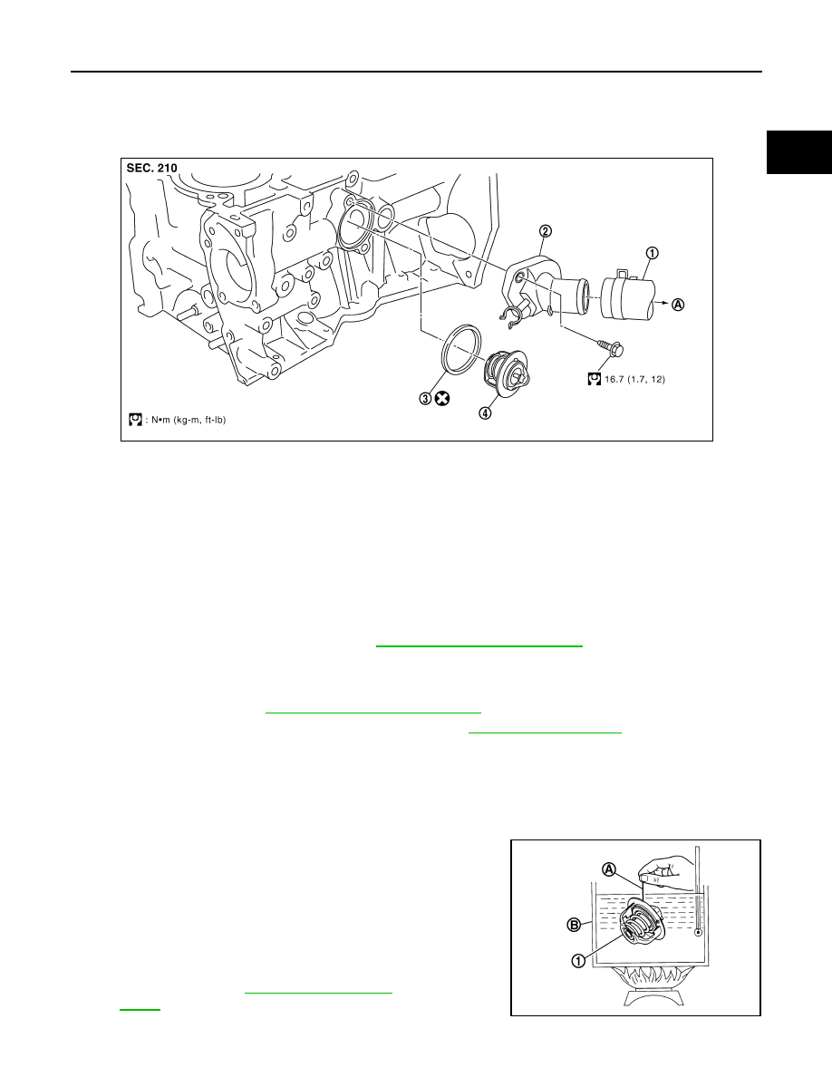
Exploded View
INFOID:0000000009444804
Removal and Installation
INFOID:0000000009444805
WARNING:
Do not remove the radiator cap when the engine is hot. Serious burns could occur from high-pressure
engine coolant escaping from the radiator. Wrap a thick cloth around the radiator cap. Slowly turn it a
quarter of a turn to release built-up pressure. Carefully remove radiator cap by turning it all the way.
REMOVAL
1. Drain engine coolant from radiator. Refer to
CO-8, "Draining Engine Coolant"
CAUTION:
• Perform this step when engine is cold.
• Do not spill engine coolant on drive belt.
2. Remove air duct. Refer to
EM-26, "Removal and Installation"
.
3. Disconnect radiator hose (lower) from water inlet. Refer to
.
4. Remove water inlet, thermostat, and rubber ring.
NOTE:
Engine coolant will leak from cylinder block, so have a receptacle ready below.
INSPECTION AFTER REMOVAL
Thermostat
• Place a thread (A) so that it is caught in the valves of thermostat
(1). Immerse fully in a container (B) filled with water. Heat while
stirring.
• The valve opening temperature is the temperature at which the
valve opens and falls from the thread.
• Continue heating. Check the full open valve lift amount.
• After checking the maximum valve lift amount, lower the water
temperature and check the valve closing temperature.
• If out of the standard specification range, replace the thermostat.
1.
Radiator hose (lower)
2.
Water inlet
3.
Rubber ring
4.
Thermostat
A.
To radiator
PBIC3810E
Standard: Refer to
PBIC3314J