Nissan Versa Note. Manual - part 165


  Index      Nissan     Nissan Versa Note (2014 year) - Service and Repair Manual


Search            


Content   ..  163  164  165  166   ..


Nissan Versa Note. Manual - part 165


ENGINE COOLANT

CO-9

< PERIODIC MAINTENANCE >

[HR16DE]

C

D

E

F

G

H

I

J

K

L

M

A

CO

N

P

O

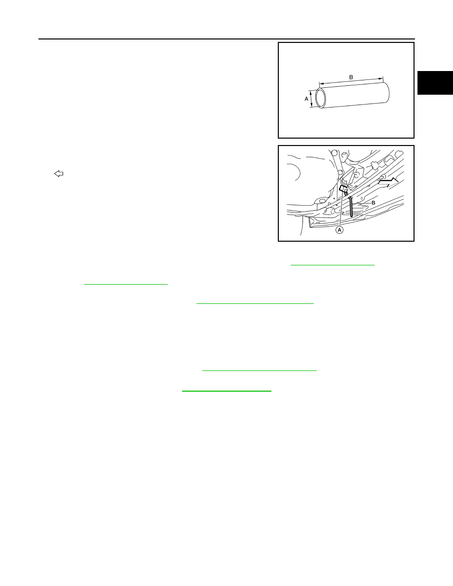
2. Connect a suitable hose to the radiator drain plug.

• Use a suitable hose with the dimensions as shown.

3. Open radiator drain plug (A) at the bottom of radiator, and then

remove radiator cap. 

(B): Suitable hose

: Front

CAUTION:

• Perform this step when engine is cold.

• Do not spill engine coolant on the drive belt.

4. It is necessary to drain the cylinder block when draining all of engine coolant in the system. To drain the

cylinder block, open the water drain plugs on cylinder block. Refer to 

EM-92, "Exploded View"

.

5. Remove reservoir tank if necessary, and drain engine coolant and clean reservoir tank before installing.

Refer to 

CO-14, "Exploded View"

.

6. Check drained engine coolant for contaminants such as rust, corrosion or discoloration. If contaminated,

flush the engine cooling system. Refer to 

CO-11, "Flushing Cooling System"

.

Refilling

INFOID:0000000009509399

1. Install the radiator drain plug. Install the reservoir tank and cylinder block drain plug, if removed for a total

system drain or for engine removal or repair.

• The radiator must be completely empty of engine coolant and water.

• Apply sealant to the threads of the cylinder block drain plug. Use Genuine High Performance

Thread Sealant or equivalent. Refer to 

MA-11, "Fluids and Lubricants"

.

2. If disconnected, reattach the upper radiator hose at the engine side.
3. Set the vehicle heater controls to the full HOT and heater ON position. Turn the vehicle ignition ON with

the engine OFF as necessary to activate the heater mode.

Diameter (A)

: 0.8 mm (0.31 in)

Length (B)

: 300 mm (11.81 in)

JPBIA4770ZZ

AWBIA1613ZZ

Radiator drain plug

Refer to 

CO-14, "Exploded View"

.

CO-10

< PERIODIC MAINTENANCE >

[HR16DE]

ENGINE COOLANT

4. Install the Tool by installing the radiator cap adapter onto the

radiator neck opening. Then attach the gauge body assembly

with the refill tube and the venturi assembly to the radiator cap

adapter.

5. Insert the refill hose into the engine coolant mixture container

that is placed at floor level. Make sure the ball valve is in the

closed position. 

• Use recommended engine coolant or equivalent. 

Refer to 

MA-11, "Fluids and Lubricants"

.

CAUTION:

Do not use any cooling system additives such as radiator

sealer. Additives may clog the cooling system and cause

damage to the engine, transmission and/or cooling system.

6. Install an air hose to the venturi assembly, the air pressure must

be within specification. 

CAUTION:

The compressed air supply must be equipped with an air dryer.

7. The vacuum gauge will begin to rise and there will be an audible hissing noise. During this process open

the ball valve on the refill hose slightly. Engine coolant will be visible rising in the refill hose. Once the refill

hose is full of engine coolant, close the ball valve. This will purge any air trapped in the refill hose.

8. Continue to draw the vacuum until the gauge reaches 28 inches

of vacuum. The gauge may not reach 28 inches in high altitude

locations, use the vacuum specifications based on the altitude

above sea level.

9. When the vacuum gauge has reached the specified amount, disconnect the air hose and wait 20 seconds

to see if the system loses any vacuum. If the vacuum level drops, perform any necessary repairs to the

system and repeat steps 6 - 8 to bring the vacuum to the specified amount. Recheck for any leaks. 

10. Place the engine coolant container (with the refill hose inserted) at the same level as the top of the radia-

tor. Then open the ball valve on the refill hose so the engine coolant will be drawn up to fill the cooling sys-

tem. The cooling system is full when the vacuum gauge reads zero.

CAUTION:

Do not allow the engine coolant container to get too low when filling, to avoid air from being drawn

into the cooling system. 

11. Remove the Tool from the radiator neck opening.
12. Fill the cooling system reservoir tank to the specified level and install the radiator cap. Run the engine to

warm up the cooling system and top up the system as necessary.

13. Install the front under cover. Refer to 

EXT-37, "FRONT UNDER COVER : Removal and Installation"

.

Tool number

: KV991J0070 (J-45695)

Engine coolant capacity 
(with reservoir tank)

: Refer to 

MA-11, "Fluids and 

Lubricants"

.

Compressed air 
supply pressure

: 549 - 824 kPa (5.6 - 8.4 kg/cm

2

80 - 119 psi)

LLIA0058E

Altitude above sea level

Vacuum gauge reading

0 - 100 m (328 ft)

: 28 inches of vacuum

300 m (984 ft)

: 27 inches of vacuum

500 m (1,641 ft)

: 26 inches of vacuum

1,000 m (3,281 ft)

: 24 - 25 inches of vacuum

LLIA0057E

ENGINE COOLANT

CO-11

< PERIODIC MAINTENANCE >

[HR16DE]

C

D

E

F

G

H

I

J

K

L

M

A

CO

N

P

O

Flushing Cooling System

INFOID:0000000009444794

1. Install radiator drain plug and reservoir tank, if removed.

CAUTION:

Be sure to clean drain plug and install with new O-ring.

2. If water drain plugs on cylinder block were removed, close and tighten them. Refer to 

EM-92, "Exploded

View"

.

3. Remove air duct from between air cleaner case and electric throttle control actuator. Refer to 

EM-26,

"Removal and Installation"

.

4. Disconnect heater hose (1) at location (

) as shown.

• Position heater hose as high as possible.

: Front

5. Fill radiator until engine coolant flows out of the disconnected heater hose and then reconnect the heater

hose.

6. Finish filling the engine and reservoir tank with water and reinstall the radiator cap.
7. Install air duct in between air cleaner case and electric throttle control actuator. Refer to 

EM-26, "Removal

and Installation"

.

8. Run the engine and warm it up to normal operating temperature.
9. Rev the engine two or three times under no-load.
10. Stop the engine and wait until it cools down.
11. Drain water from the system. Refer to 

CO-8, "Draining Engine Coolant"

.

12. Repeat steps 1 through 11 until clear water begins to drain from radiator.

Radiator drain plug

: Refer to 

CO-14, "Exploded View"

.

JSBIA0616ZZ

CO-12

< PERIODIC MAINTENANCE >

[HR16DE]

RADIATOR

RADIATOR

RADIATOR CAP
RADIATOR CAP : Inspection

INFOID:0000000009444795

• Check valve seat (A) of radiator cap. 

- Replace the cap if the metal plunger cannot be seen around the

edge of the black rubber gasket.

- Replace the cap if deposits of waxy residue or other foreign mate-

rial are on the black rubber gasket or the metal retainer.

NOTE:

Thoroughly wipe out the radiator filler neck to remove any waxy

residue or foreign material.

• Pull negative-pressure valve to open it, and check that it closes

completely when released.

- Check that there is no dirt or damage on the valve seat of radiator

cap negative-pressure valve. 

- Check that there are no abnormalities in the opening and closing

conditions of negative-pressure valve.

• Check radiator cap relief pressure using suitable tool (A) and Tool

(B).

- When connecting the radiator cap to Tool (B), apply water or

engine coolant to the cap seal surface. 

- Replace the radiator cap if there is an abnormality in the negative-

pressure valve, or if the open-valve pressure is outside of the stan-

dard values.

RADIATOR
RADIATOR : Inspection

INFOID:0000000009509401

Check radiator for mud or clogging. If necessary, clean radiator as follows.

CAUTION:

• Be careful not to bend or damage radiator fins.

• When radiator is cleaned without removal, remove all surrounding parts in order to access the radia-

tor core. Then tape harness and harness connectors to prevent water from entering.

1. Spray water to the back side of the radiator core using a side to side motion from the top down.
2. Stop spraying when debris no longer flows from radiator.
3. Blow air into the back side of radiator core using side to side motion from the top down.

• Use compressed air lower than 490 kPa (5 kg/cm

2

, 71 psi) and keep distance more than 30 cm (11.81

in). 

4. Continue to blow air until no water sprays out.

(B)

: Metal plunger

JPBIA0108ZZ

SMA967B

Tool number

: EG17650301 (J-33984-A)

Standard and Limit

: Refer to 

CO-26, "Standard and 

Limit"

.

PBIC5122J


Content   ..  163  164  165  166   ..