Nissan Versa Note. Manual - part 162
CL-18
< UNIT REMOVAL AND INSTALLATION >
CLUTCH DISC AND CLUTCH COVER
CLUTCH DISC AND CLUTCH COVER
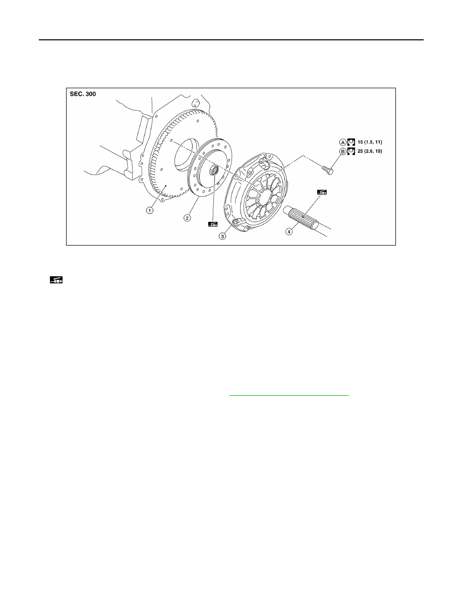
Exploded View
INFOID:0000000009417440
Removal and Installation
INFOID:0000000009417441
CAUTION:
• Do not reuse CSC (concentric slave cylinder). CSC slides back to the original position every time
when removing transaxle assembly. At this time, dust on the sliding parts may damage the seal of
CSC and may cause clutch fluid leaks.
• Do not allow any grease to contact the clutch disc facing, pressure plate surface and flywheel sur-
face.
• Do not clean clutch disc using solvent.
REMOVAL
1. Remove engine and transaxle assembly. Refer to
TM-24, "Removal and Installation"
.
2. Loosen clutch cover bolts evenly. Then remove clutch cover and clutch disc.
INSTALLATION
1. Clean clutch disc and input shaft splines to remove grease and dust caused by abrasion.
2. Apply recommended grease to clutch disc and input shaft splines.
CAUTION:
Be sure to apply grease to the points specified. Otherwise, noise, poor disengagement, or damage
to the clutch may result. Excessive grease may cause slip or shudder. If grease adheres to seal of
CSC, it may cause clutch fluid leaks. Wipe off excess grease. Wipe off any grease oozing from the
parts.
1.
Flywheel
2.
Clutch disc
3.
Clutch cover
4.
Input shaft
A.
First step
B.
Final step
: Apply lithium-based grease including molybdenum disulphide.
AWDIA0948GB