Nissan Versa Note. Manual - part 160
CL-10
< REMOVAL AND INSTALLATION >
CLUTCH PEDAL
REMOVAL AND INSTALLATION
CLUTCH PEDAL
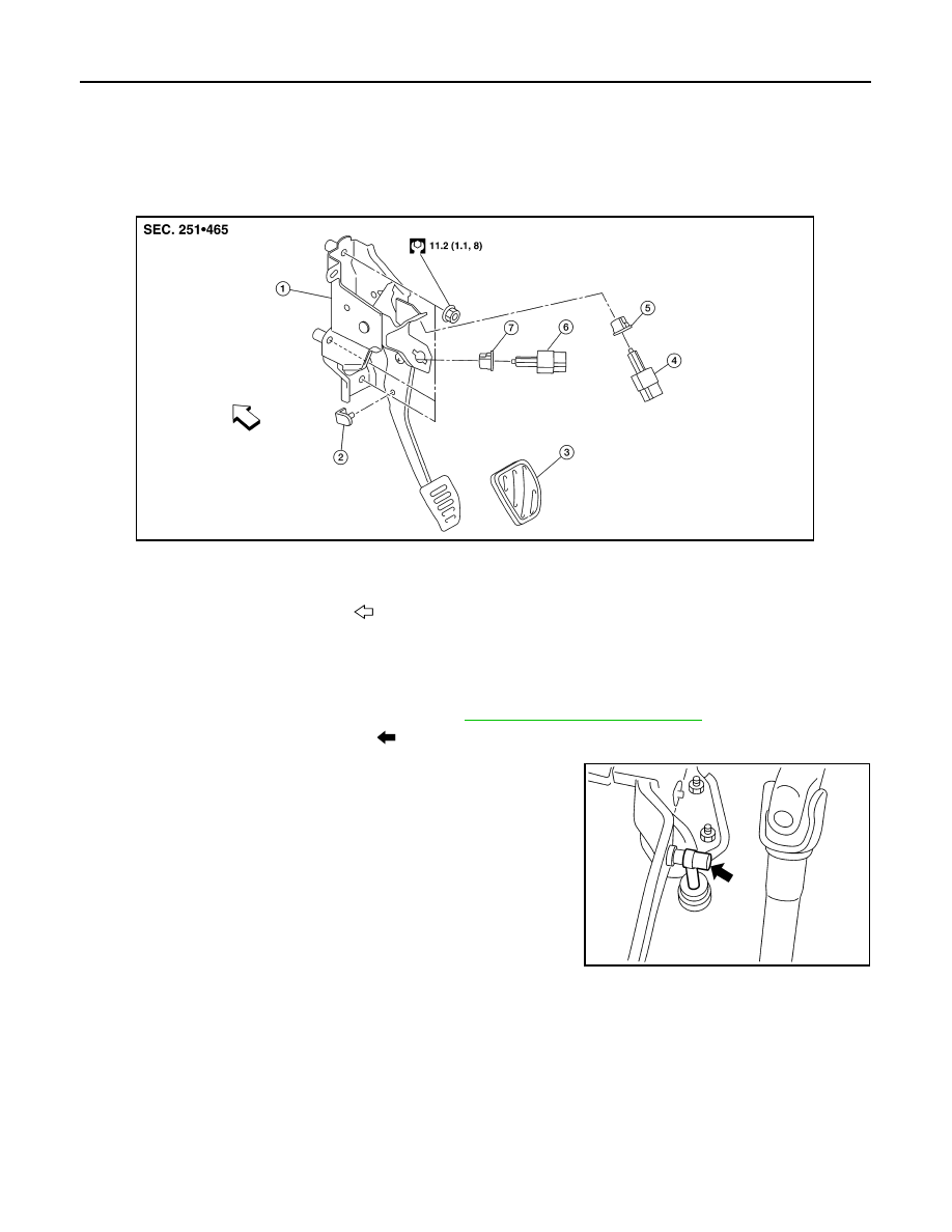
Exploded View
INFOID:0000000009417427
Removal and Installation
INFOID:0000000009417428
REMOVAL
1. Remove the instrument lower panel LH. Refer to
IP-24, "Removal and Installation"
.
2. Disconnect master cylinder rod end (
) from clutch pedal.
3. Disconnect ASCD cancel switch and clutch interlock switch harness connector
4. Remove harness clip from clutch pedal.
5. Remove clutch pedal nuts and remove clutch pedal.
6. Remove pedal pad from clutch pedal.
7. Remove clutch interlock switch and clip from clutch pedal.
8. Remove pedal stopper rubber from clutch pedal using a suitable tool.
INSTALLATION
Installation is in the reverse order of removal.
CAUTION:
Press master cylinder rod end into clutch pedal until it stops.
1.
Clutch pedal
2.
Pedal stopper rubber
3.
Pedal pad
4.
Clutch interlock switch
5.
Clip
6.
ASCD cancel switch
7.
Clip
Front
ALBIA1141ZZ
PCIB1491E