Nissan Versa Note. Manual - part 137
BRC-112
< REMOVAL AND INSTALLATION >
[VDC/TCS/ABS]
STEERING ANGLE SENSOR
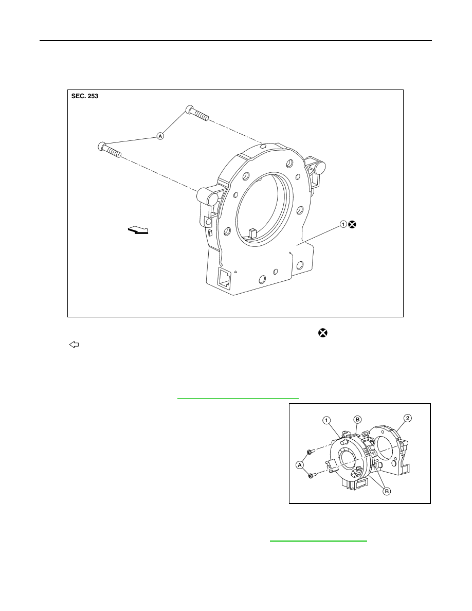
STEERING ANGLE SENSOR
Exploded View
INFOID:0000000009654075
Removal and Installation
INFOID:0000000009364977
REMOVAL
1. Remove the spiral cable. Refer to
SR-15, "Removal and Installation"
.
2. Remove the screws (A), then release the pawls (B) and remove
the steering angle sensor (2) from the spiral cable (1).
INSTALLATION
Installation is in the reverse order of removal.
Adjust the neutral position of the steering angle sensor. Refer to
CAUTION:
Do not reuse steering angle sensor.
1.
Steering angle sensor
A.
Screw
Do not reuse
Front
ALFIA0235ZZ
ALHIA0271ZZ