Nissan Versa Note. Manual - part 123
BRC-56
< DTC/CIRCUIT DIAGNOSIS >
[VDC/TCS/ABS]
C1101, C1102, C1103, C1104 WHEEL SENSOR
1. Disconnect ABS actuator and electric unit (control unit) connector E33 and wheel sensor connector of
suspect wheel.
2. Check harness, connectors and terminals for corrosion, deformation, disconnection, looseness or dam-
age.
Is the inspection result normal?
YES
>> GO TO 4.
NO
>> Repair or replace as necessary.
4.
CHECK WHEEL SENSOR OUTPUT SIGNAL
1. Connect ABS active wheel sensor tester (J-45741) to wheel sensor using appropriate adapter.
2. Turn on the ABS active wheel sensor tester power switch.
NOTE:
The green POWER indicator should illuminate. If the POWER indicator does not illuminate, replace the
battery in the ABS active wheel sensor tester before proceeding.
3. Spin the wheel of the vehicle by hand and observe the red SENSOR indicator on the ABS active wheel
sensor tester. The red SENSOR indicator should flash ON and OFF to indicate an output signal.
NOTE:
If the red SENSOR indicator illuminates but does not flash, reverse the polarity of the tester leads and
retest.
Does the ABS active wheel sensor tester detect a signal?
YES
>> GO TO 5.
NO
>> Replace the wheel sensor. Refer to
BRC-105, "FRONT WHEEL SENSOR : Removal and Installa-
or
BRC-106, "REAR WHEEL SENSOR : Removal and Installation"
5.
CHECK WIRING HARNESS FOR SHORT TO VOLTAGE
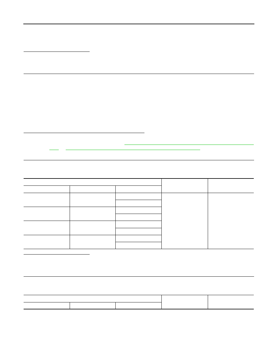
1. Turn ignition switch ON.
2. Check voltage between wheel sensor harness connector terminals of suspect wheel and ground.
Is the inspection result normal?
YES
>> GO TO 6.
NO
>> Repair the circuit.
6.
CHECK WIRING HARNESS FOR SHORT TO GROUND
1. Turn ignition switch OFF.
2. Check continuity between wheel sensor harness connector terminals of suspect wheel and ground.
Wheel Sensor
Ground
Voltage
Wheel
Connector
Terminal
Front LH
E51
1
—
0V
2
Front RH
E52
1
2
Rear LH
B22
1
2
Rear RH
B35
1
2
Wheel Sensor
Ground
Continuity
Wheel
Connector
Terminal