Nissan Versa Note. Manual - part 50
AV-192
< DTC/CIRCUIT DIAGNOSIS >
[NAVIGATION]
U111B SIDE CAMERA RH IMAGE SIGNAL CIRCUIT
3. Check continuity between around view monitor control unit connector B54 and RH side camera connector
D107.
4. Check continuity between around view monitor control unit connector B54 and ground.
Is the inspection result normal?
YES
>> GO TO 4.
NO
>> Repair or replace harness or connectors.
4.
CHECK RH SIDE CAMERA IMAGE SIGNAL
1. Connect around view monitor control unit and RH side camera connectors.
2. Turn ignition switch ON.
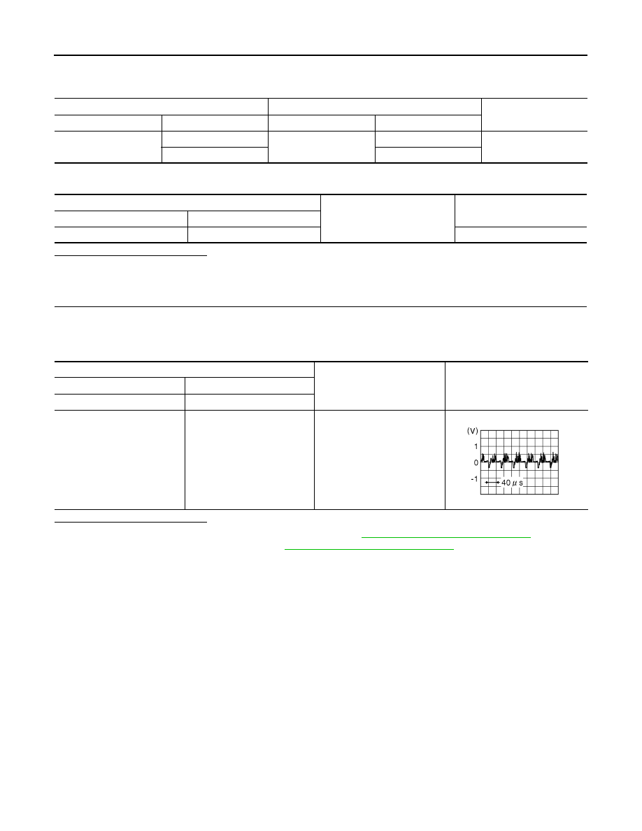
3. Check signal between the terminals of around view monitor control unit connector B54.
Is the inspection result normal?
YES
>> Replace around view monitor control unit. Refer to
AV-248, "Removal and Installation"
NO
>> Replace RH side camera. Refer to
AV-251, "Removal and Installation"
Around view monitor control unit
RH side camera
Continuity
Connector
Terminals
Connector
Terminals
B54
36
D107
8
Yes
35
7
Around view monitor control unit
Ground
Continuity
Connector
Terminal
B54
36
No
Around view monitor control unit connector B54
Condition
Reference value
(+)
(
−)
Terminal
Terminal
36
35
CAMERA switch is ON or se-
lector lever in R (reverse).
JSNIA0834GB