Nissan Versa Note. Manual - part 21


  Index      Nissan     Nissan Versa Note (2014 year) - Service and Repair Manual


Search            


Content   ..  19  20  21  22   ..


Nissan Versa Note. Manual - part 21


AV-76

< SYSTEM DESCRIPTION >

[DISPLAY AUDIO]

DIAGNOSIS SYSTEM (AUDIO UNIT)
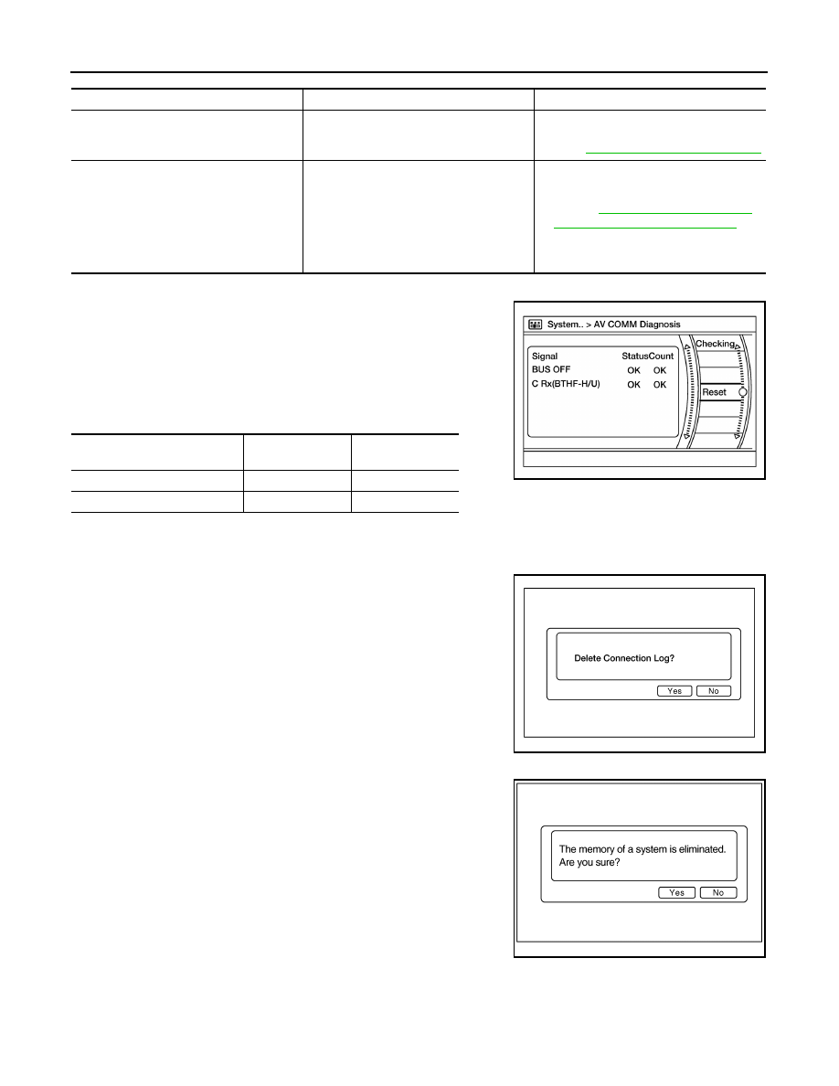
AV COMM Diagnosis

• Displays the communication status between audio unit (master

unit) and Bluetooth

®

 control unit.

• The error counter displays OK if any malfunction was not detected

in the past and displays 0 if a malfunction is detected. It increases

by 1 if the condition is normal at the next ignition switch ON cycle.

The upper limit of the counter is 39.

• The error counter is erased if Reset is pressed.

NOTE:

“???” indicates UNKWN.

Delete Unit Connection Log

Deletes any unit connection records and error records from the

audio unit memory (clears the records of the unit that has been

removed).

Initialize Settings

Deletes data stored from the audio unit.

Error item

Description

Possible cause

CONTROL UNIT (AV)

AV communication circuit initial diagnosis 
malfunction is detected.

Replace the audio unit if the malfunction 
occurs constantly.
Refer to 

AV-118, "Removal and Installation"

AV COMM CIRCUIT

When one of the following is detected:
• malfunction is detected in Bluetooth

®


control unit power supply and ground cir-
cuits.

• malfunction is detected in AV communi-

cation circuits between audio unit and 
Bluetooth

®

 control unit.

• Bluetooth

®

 control unit power supply or 

ground circuits.
Refer to 

AV-97, "BLUETOOTH® CON-

TROL UNIT : Diagnosis Procedure"

.

• AV communication circuits between au-

dio unit and Bluetooth

®

 control unit.

Items

Status

(Current)

Counter

(Past)

BUS OFF

OK / ???

OK / 0 – 39

C Rx(BTHF-H/U)

OK / ???

OK / 0 – 39

AWNIA2833GB

AWNIA2637GB

JSNIA0155GB

AV

DIAGNOSIS SYSTEM (BLUETOOTH® CONTROL UNIT)

AV-77

< SYSTEM DESCRIPTION >

[DISPLAY AUDIO]

C

D

E

F

G

H

I

J

K

L

M

B

A

O

P

DIAGNOSIS SYSTEM (BLUETOOTH® CONTROL UNIT)

Diagnosis Description

INFOID:0000000009681867

The Bluetooth

®

 control unit has two diagnostic checks. The first diagnostic check is performed automatically

every ignition cycle during control unit initialization. The second diagnostic check is performed by the techni-

cian using the steering wheel audio control switches prior to trouble diagnosis.

Bluetooth

®

 CONTROL UNIT INITIALIZATION CHECKS

• Internal control unit failure
• Bluetooth

®

 antenna connection open or shorted

• Steering wheel audio control switches [

 (PHONE/SEND),   (PHONE/END)] stuck closed

• Vehicle speed pulse count

• Microphone connection test (with playback to operator)
• Bluetooth

®

 inquiry check

OPERATION PROCEDURE

1. Turn ignition switch to ACC or ON.
2. Wait for the Bluetooth

®

 system to complete initialization. This may take up to 20 seconds.

3. Press and hold the steering wheel audio control switch 

(PHONE/SEND) button for at least 5 seconds. The Bluetooth

®

system will begin to play a verbal prompt.

4. While the prompt is playing, press and hold the steering wheel

audio control switch   (PHONE/END) button until you hear the
“Diagnostics mode” prompt. The Bluetooth

®

 system will sound a

5-second beep.

5. While the beep is sounding, press and hold the steering wheel

audio control switch 

 (PHONE/END) button again until you

hear prompts.

6. The Bluetooth

®

 system has now entered into the diagnostic

mode. Results of the diagnostic checks will be verbalized to the

technician. Refer to 

AV-77, "Work Flow"

.

7. After the failure records are reported, an interactive microphone

test will be performed. Follow the voice prompt. If the micro-

phone test fails, refer to 

AV-77, "Work Flow"

.

Work Flow

INFOID:0000000009459955

AWNIA3082ZZ

AWNIA3083ZZ

Failure Message

Action

“Internal failure”

Replace Bluetooth

®

 control unit. Refer to 

AV-123, "Removal and Installation"

“Bluetooth

®

 antenna open”

1.

Inspect harness connection.

2.

Replace Bluetooth

®

 antenna. Refer to 

AV-124, "Removal and Installation"

.

“Bluetooth

®

 antenna shorted”

“Phone/Send for Hands Free System is stuck”

Check steering wheel audio control switches. Refer to 

AV-110, "Diagnosis Proce-

dure"

.

“Phone/End for the Hands Free System is stuck”

“Microphone test” (failed interactive test)

1.

Inspect harness between Bluetooth

®

 control unit and microphone.

2.

Replace microphone. Refer to 

AV-126, "Removal and Installation"

 .

AV-78

< ECU DIAGNOSIS INFORMATION >

[DISPLAY AUDIO]

AUDIO UNIT

ECU DIAGNOSIS INFORMATION

AUDIO UNIT

Reference Value

INFOID:0000000009459956

TERMINAL LAYOUT

PHYSICAL VALUES

AWNIA2820ZZ

Terminal

(Wire color)

Description

Condition

Reference value

(Approx.)

+

Signal name

Input/

Output

Ignition 

switch

Operation

2

(GR)

3

(P)

Sound signal front door 
speaker LH

Output

ON

Sound output

4

(W)

5

(R)

Sound signal rear door 
speaker LH

Output

ON

Sound output

6

(BR)

15

(GR)

Steering switch signal A

Input

ON

Press SOURCE switch

 0V

Press  

switch

1.0V

Press  

switch

2.0V

Press  

switch

3.0V

Except above

5.0V

7

(W)

Ground ACC power supply

Input

ACC

Battery voltage

9

 (LG/R)

8

(B)

Illumination control signal

Input

ON

Headlamps ON

Battery voltage

SKIB3609E

SKIB3609E

AV

AUDIO UNIT

AV-79

< ECU DIAGNOSIS INFORMATION >

[DISPLAY AUDIO]

C

D

E

F

G

H

I

J

K

L

M

B

A

O

P

11

(O)

12

(V)

Sound signal front door 
speaker RH

Output

ON

Sound output

13

(L)

14

(Y)

Sound signal rear door 
speaker RH

Output

ON

Sound output

16

(V)

15

(GR)

Steering switch signal B

Input

ON

Press  

switch

0V

Press  

switch

1.0V

Press  

switch

2.0V

Except above

5.0V

18

(LG)

Ground Vehicle speed signal

Input

ON

When vehicle speed is ap-
prox. 40 km/h (25 MPH)

19

(Y)

Ground Battery power supply

Input

OFF

Battery voltage

20

(B/W)

Ground Ground

ON

0 V

25

(G)

24

(R)

TEL voice signal

Input

ON

During voice guide output 
with 

 switch pressed.

26

(Shield)

TEL voice signal shield

31

(SB)

AV communication (H)

Input/

Output

32

(LG)

AV communication (L)

Input/

Output

33

(B)

Ground Camera ground

ON 

0 V

34

(L)

Ground Camera power supply

Output

ON

Camera image displayed

6.0 V

Except for above

0 V

Terminal

(Wire color)

Description

Condition

Reference value

(Approx.)

+

Signal name

Input/

Output

Ignition 

switch

Operation

SKIB3609E

SKIB3609E

JSNIA0012GB

SKIB3609E


Content   ..  19  20  21  22   ..