Nissan Versa Note. Manual - part 22
AV-80
< ECU DIAGNOSIS INFORMATION >
[DISPLAY AUDIO]
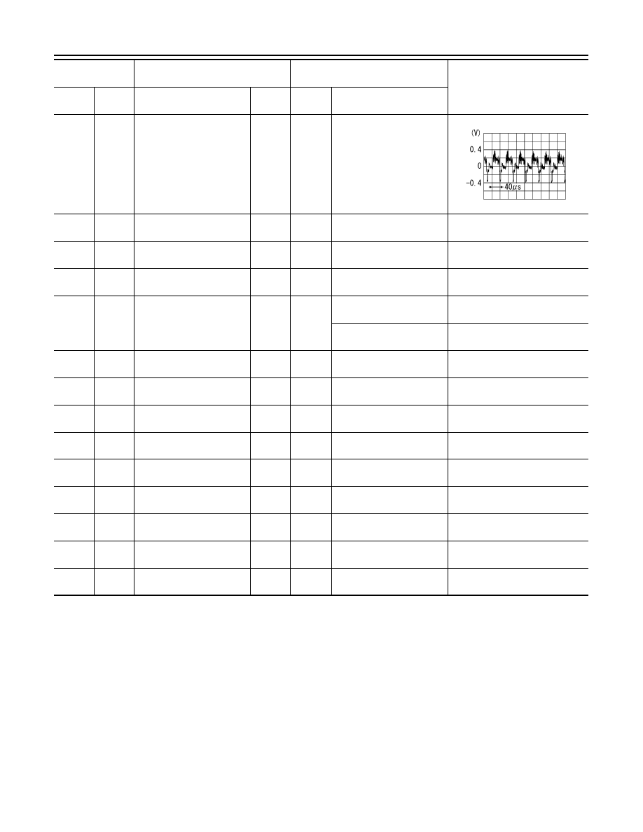
AUDIO UNIT
35
(Y)
36
(Shield)
Camera image signal
Input
ON
Camera image displayed
44
(B)
Ground Camera detection
—
ON
—
0 V
46
(B)
Ground EQ02 Ground
—
ON
—
0 V
48
(B/W)
Ground EQ04 Ground
—
ON
—
0 V
50
(Y)
Ground Reverse signal
Input
ON
Selector lever in R (re-
verse)
Battery voltage
Selector lever in any posi-
tion other than R (reverse)
0 V
53
(W)
—
V BUS signal
—
—
—
—
54
(G)
—
USB ground
—
—
—
—
55
(L)
—
USB D+ signal
—
—
—
—
56
(R)
—
USB D
− signal
—
—
—
—
57
(Shield)
—
USB shield
—
—
—
—
58
(B)
Ground Antenna amp. ON signal
Output
ON
Audio unit ON, FM-AM se-
lected.
Battery voltage
59
(B)
Ground AM/FM antenna signal
Input
ON
Audio unit ON, FM-AM se-
lected.
5.0 V
61
(B)
Ground Satellite antenna signal
Input
ON
Audio unit ON, XM select-
ed.
5.0 V
62
(Shield)
—
Satellite antenna shield
—
—
—
—
Terminal
(Wire color)
Description
Condition
Reference value
(Approx.)
+
–
Signal name
Input/
Output
Ignition
switch
Operation
SKIB2251J