Nissan Rogue. Manual - part 978


  Index      Nissan     Nissan Rogue (2015 year) - Service and Repair Manual


Search            


Content   ..  976  977  978  979   ..


Nissan Rogue. Manual - part 978


PG

FUSE INSPECTION

PG-75

< BASIC INSPECTION >

C

D

E

F

G

H

I

J

K

L

B

A

O

P

N

1. Turn the ignition switch OFF.

2. Turn the extended storage fuse switch OFF.
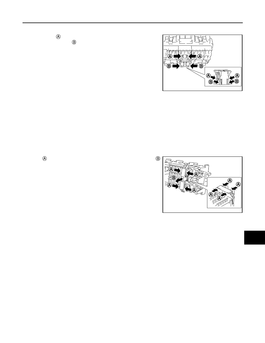
3. Press pawl   and tilt to disengage the extended storage fuse

switch. Press pawl   and tilt to remove the extended storage

fuse switch.

CAUTION:

Never use fuse for bus bar.

NOTE:

• Extended storage fuse switch and bus bar are removed together. Remove bus bar from extended stor-

age fuse switch, if necessary.

• Install removed bus bar to fuse block.

• Extended storage fuse switch is for transportation and storage. Reinstallation is not required after the

removal.

Type B

1. Turn the ignition switch OFF.

2. Turn the extended storage fuse switch OFF.
3. Hold   and pull up the extended storage fuse switch hard in 

direction.

CAUTION:

Never use fuse for bus bar.

NOTE:

• Extended storage fuse switch and bus bar may be removed together. Remove bus bar from extended

storage fuse switch, if necessary.

• Install removed bus bar to fuse block.

• Extended storage fuse switch is for transportation and storage. Reinstallation is not required after the

removal.

Type C

1. Turn the ignition switch OFF.

2. Turn the extended storage fuse switch OFF.

JSMIA0476ZZ

JSMIA0477ZZ

PG-76

< BASIC INSPECTION >

FUSE INSPECTION

3. Hold   and pull up the extended storage fuse switch hard in 

direction.

CAUTION:

Never use fuse for bus bar.

NOTE:

• Extended storage fuse switch and bus bar are removed together. Remove bus bar from extended stor-

age fuse switch, if necessary.

• Install removed bus bar to fuse block.

• Extended storage fuse switch is for transportation and storage. Reinstallation is not required after the

removal.

JSMIA0795ZZ

PG

FUSIBLE LINK INSPECTION

PG-77

< BASIC INSPECTION >

C

D

E

F

G

H

I

J

K

L

B

A

O

P

N

FUSIBLE LINK INSPECTION

Fusible Link

INFOID:0000000011280959

A melted fusible link can be detected either by visual inspection or by feeling with finger tip. If its condition is

questionable, use circuit tester or test lamp.

CAUTION:

• If fusible link should melt, it is possible that critical circuit (power supply or large current carrying

circuit) is shorted. In such a case, carefully check and eliminate cause of malfunction.

• Never wrap outside of fusible link with vinyl tape. Important: Never let fusible link touch any other

wiring harness, vinyl or rubber parts.

1

: Fusible link

JPMIA0516ZZ

PG-78

< REMOVAL AND INSTALLATION >

BATTERY

REMOVAL AND INSTALLATION

BATTERY

Exploded View

INFOID:0000000011280960

Removal and Installation (Battery)

INFOID:0000000011280961

REMOVAL

1. Pull back cover of battery positive terminal.
2. Loosen the battery terminal nuts and disconnect the battery negative and positive terminals. 

CAUTION:

To prevent damage to the parts, disconnect the battery negative terminal first.

3. Remove battery frame nuts, battery frame and battery rods.
4. Remove battery cover and battery.

INSTALLATION

Installation is in the reverse order of removal.

WARNING:

Do not allow battery fluid to come into contact with skin, eyes, fabrics, or painted surfaces. After

touching a battery, never touch or rub your eyes until you have thoroughly washed your hands. If acid

contacts eyes, skin or clothing, immediately flush with water for 15 minutes and seek medical atten-

tion. Failure to do this may cause personal injury or damage to clothing or the painted surfaces.

1.

Battery frame

2.

Battery

3.

Battery rod

4.

Battery cover

5.

Battery tray liner

6.

Battery tray

Front

AWMIA1614ZZ


Content   ..  976  977  978  979   ..