Nissan Rogue. Manual - part 918
MWI
DIAGNOSIS SYSTEM (COMBINATION METER)
MWI-19
< SYSTEM DESCRIPTION >
C
D
E
F
G
H
I
J
K
L
M
B
A
O
P
DIAGNOSIS SYSTEM (COMBINATION METER)
Description
INFOID:0000000011279787
COMBINATION METER SELF-DIAGNOSIS MODE
The following meter functions can be checked during Combination Meter Self-Diagnosis Mode:
• Pointer sweep of speedometer, tachometer and gauges.
• Illumination of all LCD segments and color patterns for meter displays.
• Illumination of all lamps/LEDs that are controlled by the combination meter (regardless of switch status).
STARTING COMBINATION METER SELF-DIAGNOSIS MODE
NOTE:
• Check combination meter power supply and ground circuits if self-diagnosis mode does not start. Refer to
MWI-60, "COMBINATION METER : Diagnosis Procedure"
. Replace combination meter if power supply and
ground circuits are found to be normal and self-diagnosis mode does not start. Refer to
• Combination meter self-diagnosis mode will function with the ignition switch in ON. Combination meter self-
diagnosis mode will exit upon turning the ignition switch to OFF.
How to Initiate Self-Diagnosis Mode
1. Turn ignition switch OFF.
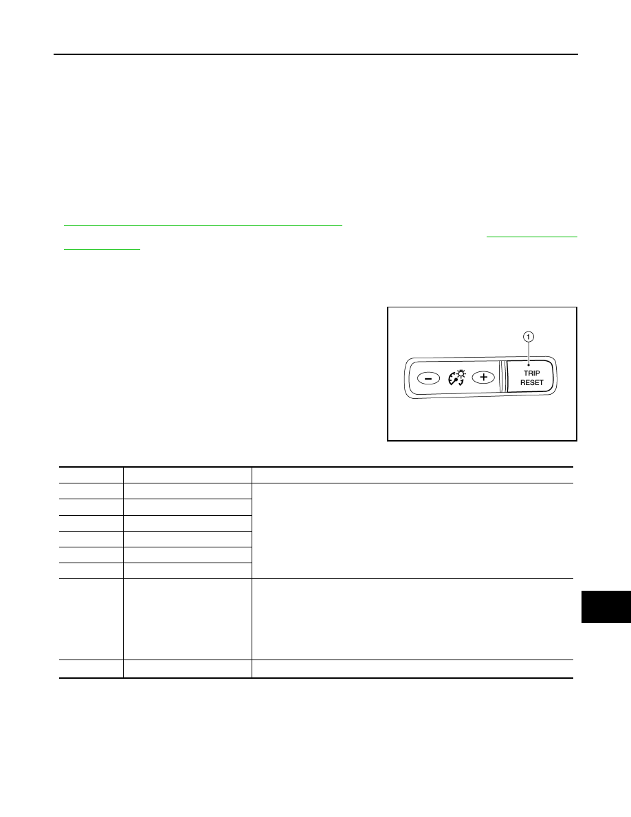
2. While pressing the trip reset switch (1), turn ignition switch ON.
3. Keep the trip reset switch for 1 seconds or more.
4. Press the trip reset switch at least 3 times. (Within 7 seconds
after the ignition switch is turned ON.)
5. “Work instruction code” is indicated in the top portion of informa-
tion display and self-diagnosis is started.
6. The mode switches in the order shown below each time the trip
reset switch is pressed.
NOTE:
If the trip reset switch is not operated for 20 seconds or more, the
self-diagnosis mode is automatically cancelled.
AWNIA3394ZZ
Test order
Test item
Description
1
Work instruction code
This item is displayed, but not used.
2
Part number
3
Software code
4
EEPROM code
5
Hardware code
6
P.C.B code
7
Circuit check
The pointer of the following items moves from 0 to MAX twice.
• Speedometer
• Tachometer
• Engine coolant temperature gauge
• Fuel gauge
NOTE:
If any one of the pointers does not sweep, replace combination meter.
8
Color check
*1
Performs the color check of the information display.