Nissan Rogue. Manual - part 917


  Index      Nissan     Nissan Rogue (2015 year) - Service and Repair Manual


Search            


Content   ..  915  916  917  918   ..


Nissan Rogue. Manual - part 917


MWI

SYSTEM

MWI-15

< SYSTEM DESCRIPTION >

C

D

E

F

G

H

I

J

K

L

M

B

A

O

P

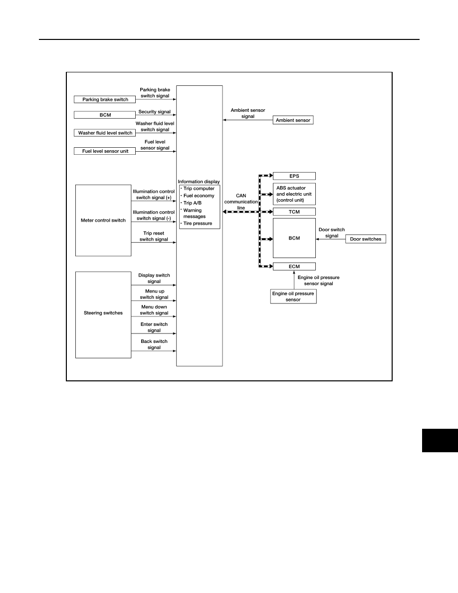
INFORMATION DISPLAY : System Description

INFOID:0000000011279784

SYSTEM DIAGRAM

FUNCTION

The information display can indicate the following items:

• Outside air temperature

• Trip computer

• Intelligent Key operation information

• CVT shift position indicator

• Odometer

• Warning/Indication messages (door open, lift gate open, low oil pressure, CVT, AWD, I-Key, low fuel, low

washer fluid, release parking brake, low tire pressure and loose fuel cap).

OUTSIDE AIR TEMPERATURE INDICATION

The combination meter receives the ambient sensor signal and displays the ambient temperature in the infor-

mation display.

LOOSE FUEL CAP MESSAGE

The LOOSE FUEL CAP message will display in the information display when the fuel-filler cap is not tightened

correctly. The message will turn off as soon as the ECM detects the fuel-filler cap is properly tightened. The

ECM provides a loose fuel cap signal to the combination meter via CAN communication lines.

LOW TIRE PRESSURE WARNING

AWNIA3719GB

MWI-16

< SYSTEM DESCRIPTION >

SYSTEM

This warning appears when the BCM detects low inflation pressure or a system malfunction. The BCM sends

a signal to the combination meter via CAN communication to illuminate the low tire pressure warning lamp. In

addition, a warning message will be displayed in the vehicle information display. 

DOOR OPEN WARNING

This warning appears when the ignition switch is ON and the door is open. The BCM receives a door switch

signal from the door open door switch. The BCM sends the door switch signal to the combination meter via

CAN communication lines. 

LIFTGATE OPEN WARNING

This warning appears when the ignition switch is ON and the liftgate is opened. The BCM receives a back door

switch signal from the back door switch. The BCM sends the door switch signal to the combination meter via

CAN communication lines. 

LOW FUEL WARNING

This warning appears when the fuel level in the fuel tank is low. 

LOW WINDSHIELD WASHER FLUID WARNING

When the windshield washer fluid level is low, the washer fluid level switch provides a ground signal to the

combination meter and the warning is displayed. Once fluid is added, the switch opens and the warning is no

longer displayed. 

RELEASE PARKING BRAKE WARNING

When the parking brake is applied, the parking brake switch provides a ground signal to the combination

meter. When the vehicle speed is greater than 4 MPH (7 km/h), the message is displayed and the warning

chime sounds. 

SHIFT POSITION INDICATOR

The combination meter activates the shift position indicator and manual mode information based on signals

received from TCM via CAN communication. 

LOW OIL PRESSURE WARNING

The low oil pressure warning appears in the information display when the combination meter receives a low

engine oil pressure signal from the ECM via CAN communication. 

WARNING CHECK INDICATION

The combination meter can cause an interrupt on the information display to indicate a warning, based on sig-

nals received from each unit and switch.

Refer to Owner’s Manual for additional information display items.

COMPASS
COMPASS : Description

INFOID:0000000011279785

DESCRIPTION

With the ignition switch in the ON position, and the mode or (N)

switch ON, the compass display will indicate the direction the vehicle

is heading.

Vehicle direction is displayed as follows:

• N: north

• E: east

• S: south

• W:  west

ZONE VARIATION SETTING PROCEDURE

The difference between magnetic north and geographical north can sometimes be great enough to cause

false compass readings. This difference is known as variance. In order for the compass to operate properly

(accurately) in a particular zone, the zone variation must be calibrated using the following procedure. 

LKIA0447E

MWI

SYSTEM

MWI-17

< SYSTEM DESCRIPTION >

C

D

E

F

G

H

I

J

K

L

M

B

A

O

P

Zone Variation Chart

1. Determine your location on the zone map.
2. Turn the ignition switch to the ON position.
3. Press and hold the (N) switch for about 5 seconds. The current zone number will appear in the display.
4. Press the mode or (N) switch repeatedly until the desired zone number appears in the display.
Once the desired zone number is displayed, stop pressing the mode or (N) switch and the display will show a

compass direction after a few seconds.

NOTE:

Use zone number 5 for Hawaii.

CALIBRATION PROCEDURE

The compass display is equipped with an automatic correction function. If the compass display reads “CAL” or

the direction is not shown correctly, perform the correction procedure below.

1. Press and hold the (N) switch for about 10 seconds. The display

will read “CAL”.

2. Drive the vehicle slowly in a circle, in an open, safe place. The

initial calibration is completed in about 3 turns.

NOTE:

In places where the terrestrial magnetism is extremely disturbed, the

initial correction may start automatically.

WKIA4148E

LKIA0447E

MWI-18

< SYSTEM DESCRIPTION >

OPERATION

OPERATION

Switch Name and Function

INFOID:0000000011279786

STEERING SWITCH

METER CONTROL SWITCH

AWNIA3392ZZ

No.

Switch name

Operation

Description

1.

Enter/Up/Down switch

Press

The information display settings can be changed.

2.

Display switch

3.

Back switch

AWNIA3393ZZ

No.

Switch name

Operation

Description

1.

Illumination control switch

Press

An illuminance level of the back light of the combination meter can be adjusted.

2.

Trip reset switch

Press

• The trip meter can be switched between A and B.
• Trip meter A/B can be reset by pressing and holding the trip reset switch.
• A trip computer value displayed on the information display can be reset by 

pressing and holding the trip reset switch for 1 second or more.

• All trip computer values can be reset by pressing and holding the trip reset 

switch for 3 seconds or more.


Content   ..  915  916  917  918   ..