Nissan Rogue. Manual - part 900


  Index      Nissan     Nissan Rogue (2015 year) - Service and Repair Manual


Search            


Content   ..  898  899  900  901   ..


Nissan Rogue. Manual - part 900


ENGINE MAINTENANCE

MA-15

< PERIODIC MAINTENANCE >

C

D

E

F

G

H

I

J

K

L

M

B

MA

N

O

A

1. Remove the drive belt. Refer to 

MA-13, "DRIVE BELTS : Removal and Installation"

2. Remove the drive belt auto-tensioner.

INSTALLATION

Installation is in the reverse order of removal.

CAUTION:

• Install the drive belt auto-tensioner carefully so not to damage the water pump pulley.

• If there is damage greater than peeled paint, replace the drive belt auto-tensioner.

AIR CLEANER FILTER
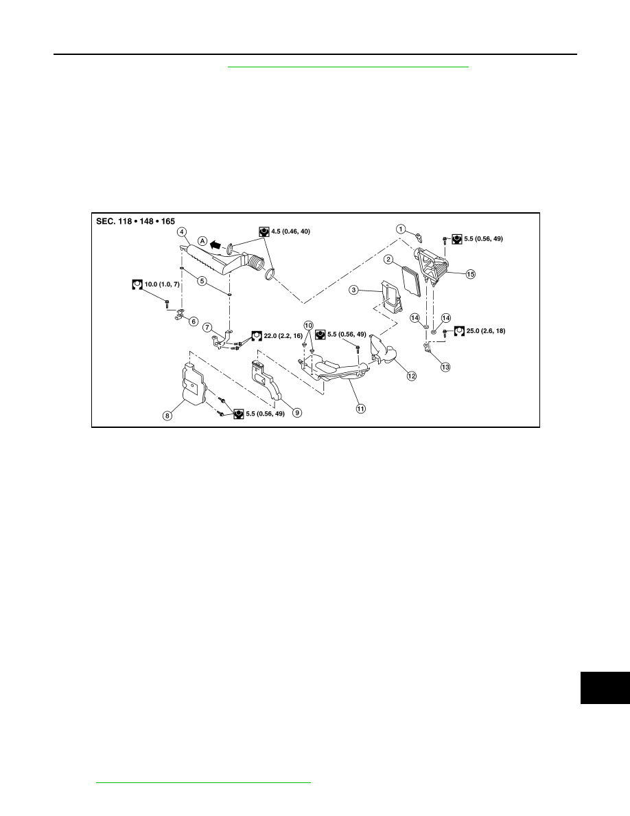
AIR CLEANER FILTER : Exploded View

INFOID:0000000011378298

AIR CLEANER FILTER : Removal and Installation

INFOID:0000000011378299

CHANGING THE AIR CLEANER FILTER

1. Remove air duct assembly from air cleaner case (upper).
2. Open the air cleaner case.
3. Remove the air cleaner filter.
4. Install a new air cleaner filter.
5. Close the air cleaner case.
6. Secure the air cleaner case clips.

INSPECTION AFTER REMOVAL

Examine the air cleaner filter for stains, clogging, or damage.

• Remove dirt and foreign objects (such as dead leaves) on air cleaner filter surface and inside cleaner case.

• If clogging or damage is observed, replace the air cleaner filter.

CAUTION:

Do not clean the viscous paper type air cleaner filter by blowing as there is a risk of deterioration of its

performance.

MAINTENANCE INTERVAL

Refer to 

MA-7, "Introduction of Periodic Maintenance"

.

1.

Mass air flow sensor

2.

Air cleaner filter

3.

Air cleaner case (lower)

4.

Air duct assembly

5.

Grommet

6.

Resonator bracket (front)

7.

Resonator bracket (rear)

8.

Resonator

9.

Air duct

10.

Mounting clip

11.

Air duct assembly

12.

Air duct assembly

13.

Air cleaner bracket

14.

Grommet

15.

Air cleaner case (upper)

A.

To Electric throttle control actuator

AWBIA2261ZZ

MA-16

< PERIODIC MAINTENANCE >

ENGINE MAINTENANCE

SPARK PLUG
SPARK PLUG : Exploded View

INFOID:0000000011378300

SPARK PLUG : Removal and Installation

INFOID:0000000011378301

REMOVAL

1. Remove air duct assembly.
2. Remove ignition coil. Refer to 

EM-41, "Exploded View"

.

3. Remove spark plug using Tool.

INSPECTION AFTER REMOVAL

Visually check the electrode for dirt and wear and the insulator for burning.

1. Ignition coil

2. Spark plug

3. Rocker cover

AWBIA1302GB

Tool number

:  —  (J-48891)

ALBIA0672GB

(A)

: Iridium alloy

AWBIA1745ZZ

ENGINE MAINTENANCE

MA-17

< PERIODIC MAINTENANCE >

C

D

E

F

G

H

I

J

K

L

M

B

MA

N

O

A

• Do not use a wire brush for cleaning the spark plugs. Replace as

necessary. 

• If plug is covered with carbon, a spark plug cleaner may be used.

• Checking and adjusting plug gap is not required between change

intervals. If the gap is out of specification, replace the spark plug.

CAUTION:

Do not drop or shock plug.

INSTALLATION

Installation is in the reverse order of removal.

*: Always check with the Parts Department for the latest parts information.

ENGINE OIL
ENGINE OIL : Inspection

INFOID:0000000011277775

ENGINE OIL LEVEL

NOTE:

Before starting engine, put vehicle horizontally and check the engine oil level. If engine is already started, stop

it and allow 5 minutes before checking.
1. Pull out oil level gauge and wipe it clean.
2. Insert oil level gauge and check the engine oil level is within the

range (A) as shown.

3. If it is out of range, adjust it.

SMA773C

Cleaner air pressure : less than 588 kPa (6 kg/cm

2

, 85 psi)

Cleaning time

: less than 20 seconds

SMA806CA

Standard type*

DENSO

FXE20HE11C

Gap (nominal)

1.1 mm (0.043 in)

PBIC3309J

MA-18

< PERIODIC MAINTENANCE >

ENGINE MAINTENANCE

ENGINE OIL APPEARANCE

• Check engine oil for white milky appearance or excessive contamination.

• If engine oil becomes turbid and white, it is highly probable that it is contaminated with engine coolant.

Repair or replace damaged parts.

ENGINE OIL LEAKS

Check for engine oil leaks around the following areas:

• Oil temperature sensor

• Oil level sensor

• Oil level gauge assembly O-ring.

• Crankshaft position sensor

• Camshaft position sensors

• Oil cooler

• Oil pan (upper and lower)

• Oil pan drain plug

• Oil pressure switch

• Oil filter

• Intake valve timing intermediate lock control solenoid valve

• Intake valve timing control solenoid valve

• Exhaust valve timing control solenoid valve

• Front cover

• Mating surface between cylinder head and camshaft bracket

• Mating surface between cylinder block and cylinder head

• Mating surface between cylinder head and rocker cover

• Crankshaft oil seals (front and rear)

OIL PRESSURE CHECK

WARNING:

• Be careful not to get burn yourself, as engine oil may be hot.

• When checking engine oil pressure, shift selector should be in "P" position. Be sure to apply parking

brake.

1. Check the engine oil level.
2. Remove fender protector side cover (RH). Refer to 

EXT-28, "FENDER PROTECTOR : Exploded View"

.

3. Disconnect harness connector at oil pressure switch and remove oil pressure switch using suitable tool.

CAUTION:

Do not drop or shock oil pressure switch.

4. Install suitable tools (A/B).

5. Start the engine and warm it up to normal operating temperature.
6. Check the engine oil pressure with engine running under no-load.

NOTE:

• When engine oil temperature is low, engine oil pressure becomes high.

• If difference is extreme, check oil passage and oil pump for engine oil leaks.

7. After the inspections, install oil pressure switch as follows:
a. Remove old liquid gasket adhering to oil pressure switch and engine.
b. Apply liquid gasket and tighten oil pressure switch to the specification.

JPBIA0074ZZ

Engine oil pressure

: Refer to 

LU-18, "Oil Pressure"

.


Content   ..  898  899  900  901   ..