Nissan Rogue. Manual - part 832
LAN
SYSTEM
LAN-27
< SYSTEM DESCRIPTION >
[CAN]
C
D
E
F
G
H
I
J
K
L
B
A
O
P
N
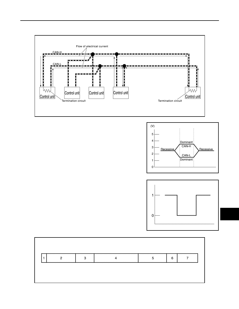
• Termination circuits (resistors) are connected across the CAN communication system. When transmitting a
CAN communication signal, each control unit passes a current to the CAN-H line and the current returns to
the CAN-L line.
• The current flows separately into the termination circuits connected
across the CAN communication system and the termination cir-
cuits drop voltage to generate a potential difference between the
CAN-H line and the CAN-L line.
NOTE:
A signal with no current passage is called “Recessive” and one
with current passage is called “Dominant”.
• The system produces digital signals for signal communications, by
using the potential difference.
The Construction of CAN Communication Signal (Message)
JSMIA0450GB
JSMIA0543GB
JSMIA0544ZZ
JSMIA0545ZZ